Bridge pier structure and construction method thereof

A construction method and bridge pier technology, applied in bridges, bridge parts, bridge construction, etc., can solve the problems of complex process, construction quality and durability need to be further improved, achieve mature technology, alleviate the impact of urban traffic environment, and shorten the construction period. Effect

Pending Publication Date: 2018-09-07
FUJIAN UNIV OF TECH
View PDF11 Cites 6 Cited by
  • Summary
  • Abstract
  • Description
  • Claims
  • Application Information

AI Technical Summary

Problems solved by technology

Traditional prefabricated bridges mostly use full-section prefabrication, which requires large-scale lifting equipment. The connection methods such as grouting sleeve connection or grouting metal bellows used in the joints require high construction accuracy and inspection of grouting construction quality. Therefore, the on-site The splicing process is more complicated, especially the construction quality and durability of the spliced ​​joints need to be further improved

Method used


Image

  • Bridge pier structure and construction method thereof
  • Bridge pier structure and construction method thereof
  • Bridge pier structure and construction method thereof

Examples


Embodiment 1

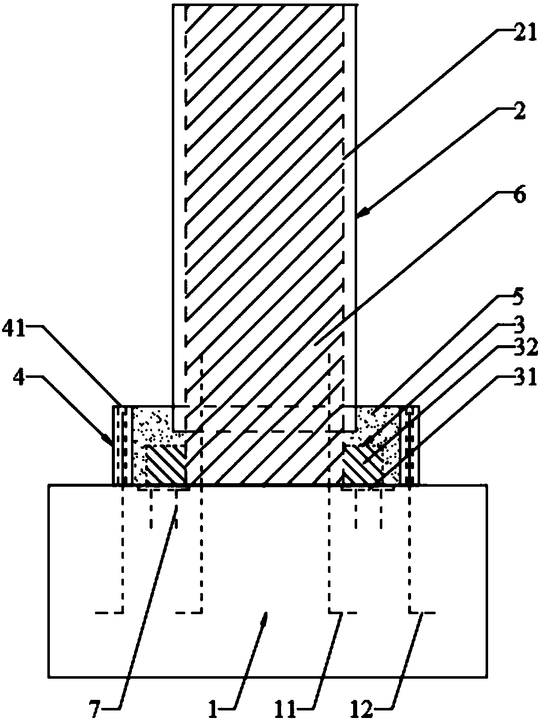
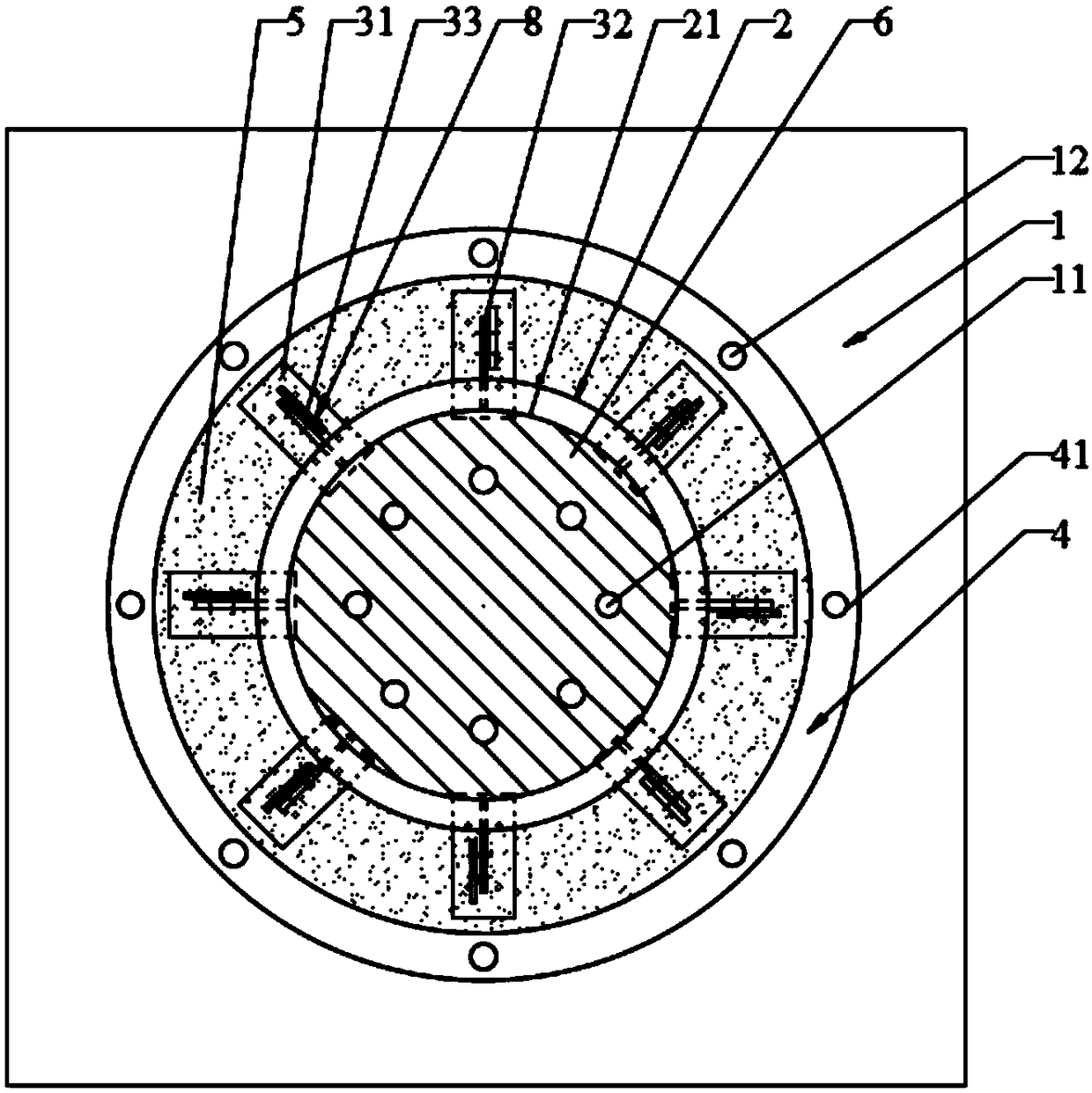
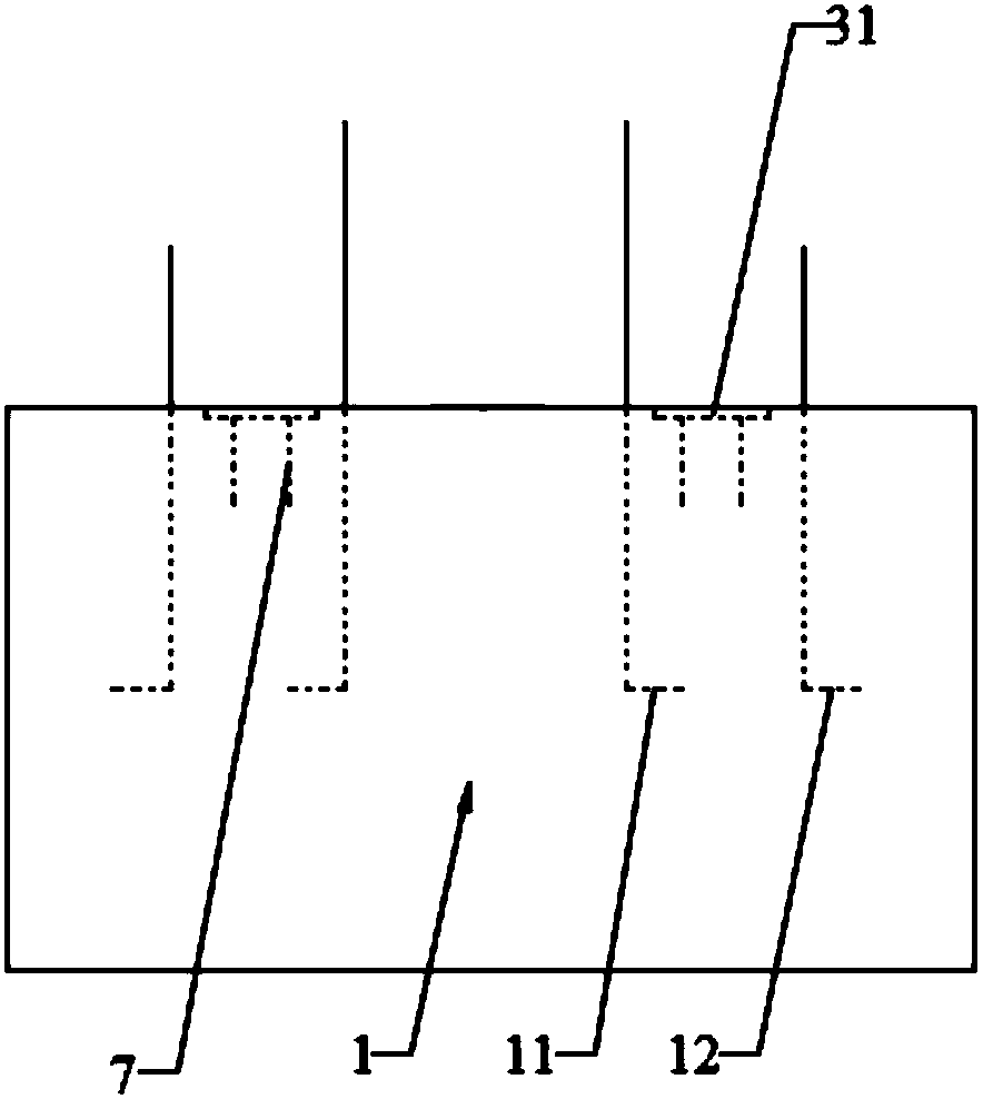
[0073] Please refer to Figure 1 to Figure 8 As shown, a bridge pier structure includes a prefabricated bridge pier 1, a prefabricated bridge pier 2, a steel plate assembly 3 and a thin-walled ring 4; the prefabricated bearing platform 1 is pre-embedded with two groups of vertically arranged and evenly distributed circumferentially. The first steel bar 11 and the second steel bar 12, the first steel bar 11 is located at the inner side of the second steel bar 12, and the top ends of the first steel bar 11 and the second steel bar 12 all protrude from the upper surface of the prefabricated platform 1; The prefabricated pier 2 is pre-embedded with a hollow steel pipe 21 that runs through the prefabricated pier 2 and is arranged in the vertical direction. The prefabricated pier 2 is arranged on the prefabricated platform 1 through the hollow steel pipe 21. The upper surface of the prefabricated pier 2 is flush, and the lower end surface of the hollow steel pipe 21 extends out of t...

Embodiment 2

[0077] It is the same as other structures of a bridge pier structure in Embodiment 1, except that the steel plate assembly 3 includes a first steel plate 31, a second steel plate 32 and a third steel plate 33, and the first steel plate 31 is pre-embedded in the prefabricated platform 1 Inside and between the first steel bar 11 and the second steel bar 12, the first steel plate 31 is horizontally arranged and the upper surface of the first steel plate 31 is flush with the upper surface of the prefabricated platform 1; the second steel plate 32 Vertically arranged and located between the prefabricated pier 2 and the first steel plate 31, one side of the second steel plate 32 is connected to the outer surface of the hollow steel pipe 21, the lower surface of the second steel plate 32 is connected to the upper surface of the first steel plate 31 Surface connection; the third steel plate 33 is vertically connected to the first steel plate 31 and the third steel plate 33 is connected...

Embodiment 3

[0080] Referring to a bridge pier structure in Embodiment 1, the present invention also provides a construction method for a bridge pier structure, comprising the following steps:

[0081] Step 1, fixing the prefabricated platform 1;

[0082] Step 2, passing the pre-embedded second steel bar 12 on the prefabricated cap 1 through the reserved hole 41 on the thin-walled ring 4, and fixing the thin-walled ring 4 on the prefabricated cap 1;

[0083] Step 3, the prefabricated pier 2 is fixed on the prefabricated platform 1 through the steel plate assembly 3, and the first steel bars 11 are all located in the hollow steel pipe 21 at this time;

[0084] Step 4, pouring the first post-cast self-compacting concrete 5 between the thin-walled ring 4 and the prefabricated pier 2;

[0085] Step 5. After the first post-cast self-compacting concrete 5 reaches the strength requirement, pour the second post-cast self-compacting concrete 6 in the hollow steel pipe 21 of the prefabricated pier ...


PUM


Abstract

The invention relates to the technical field of bridge construction, in particular to a bridge pier structure and a construction method thereof. The bridge pier structure comprises a prefabricated bearing platform, a prefabricated bridge pier, a steel plate assembly and a thin-walled circular ring; two groups of first steel rebars and second steel rebars which are arranged in the vertical direction and uniformly distributed in the form of a circumference; the first steel rebars are positioned on the internal sides of the second steel rebars; the top ends of the first steel rebars and the second steel rebars both extend out of the upper surface of the prefabricated bearing platform; a hollow steel tube which runs through the prefabricated bridge pier and is arranged in the vertical direction is embedded in the prefabricated bridge pier; and the prefabricated bridge pier is arranged on the prefabricated bearing platform through the hollow steel tube. The bridge pier structure has the advantages that the structural design is simple; the construction is convenient; as only a small part of later pouring concrete needs to be poured, the construction efficiency is enhanced, and the construction period of the bridge is reduced; the influence of bridge construction on city traffic environment is effectively relieved; and the assembling strength and integrity of the prefabricated bridgepier and the prefabricated bearing platform are also guaranteed.

Description

technical field [0001] The invention relates to the technical field of bridge construction, in particular to a bridge pier structure and a construction method thereof. Background technique [0002] The prefabricated pier technology has been applied in some urban viaducts and sea-crossing bridges. Traditional prefabricated bridges mostly use full-section prefabrication, which requires large-scale lifting equipment. The connection methods such as grouting sleeve connection or grouting metal bellows used in the joints require high construction accuracy and inspection of grouting construction quality. Therefore, the on-site The splicing process is more complicated, especially the construction quality and durability of the spliced ​​joints need to be further improved. To this end, a bridge pier structure and its construction method are proposed. The focus is to reduce the weight of the prefabricated part of the bridge pier, use small and medium-sized hoisting equipment for const...

Claims


Application Information

Patent Timeline
Patent Type & Authority Applications(China)
IPC IPC(8): E01D19/02E01D21/00
CPCE01D19/02E01D21/00
Inventor 林上顺谢铭勤王金泽欧智菁林文
Owner FUJIAN UNIV OF TECH
Why Eureka
Try Eureka