Electric heating floor and preparation method thereof

An electric heating floor and floor technology, applied in the field of floor heating floor manufacturing, can solve the problems of high installation and later maintenance costs, no mass production, high cost, etc., achieve low investment costs for factory construction, stable product quality, and avoid wet expansion and dry shrinkage Effect

Pending Publication Date: 2018-09-07
JIANGSU KENTIER WOOD
View PDF4 Cites 0 Cited by
  • Summary
  • Abstract
  • Description
  • Claims
  • Application Information

AI Technical Summary

Problems solved by technology

[0002] The electric heating floor has the advantages of easy room layout, fast heating speed, and uniform temperature distribution. However, there is no mass production in the market at present. The reason is that the existing electric heating floor has a complex structure, cumbersome production process, high cost, high energy consumption, and poor safety. , high installation and post-maintenance costs

Method used


Image

  • Electric heating floor and preparation method thereof
  • Electric heating floor and preparation method thereof

Examples


preparation example Construction

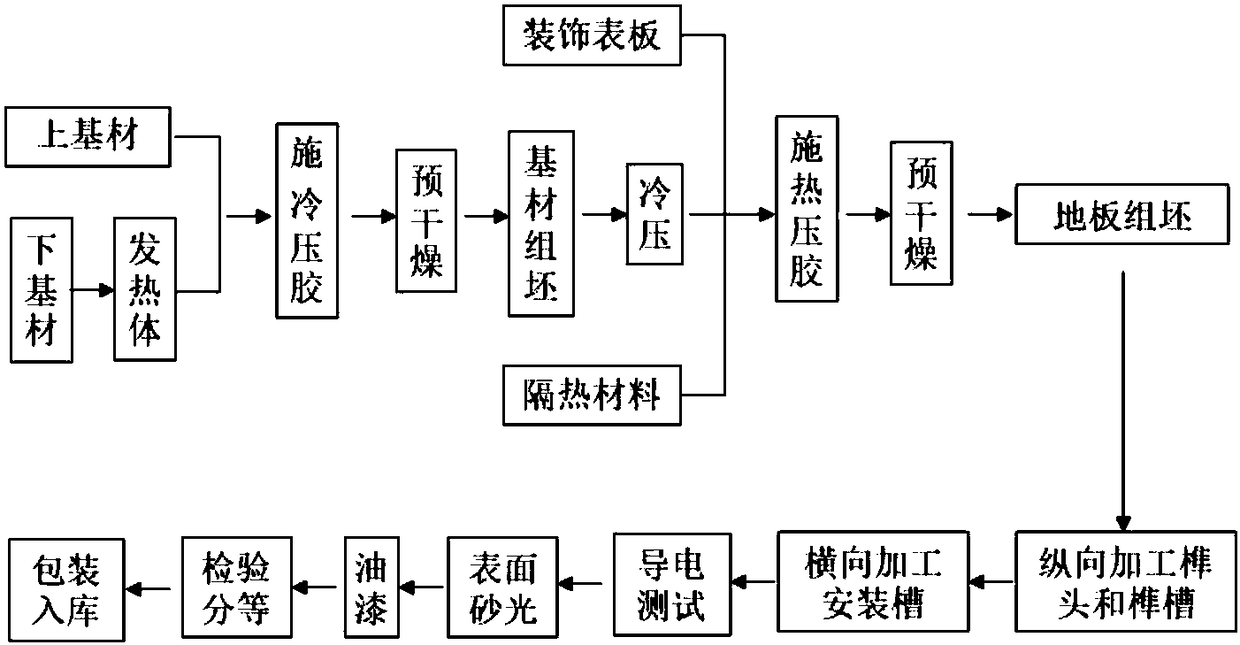
[0024] Such as figure 2 As shown, the preparation method of the electric heating floor of the present invention includes the following steps: a, raw material preparation; b, applying cold pressing glue; c, pre-drying; d, substrate assembly; Hot pressing glue; h, floor assembly; i, hot pressing; j, mortise, tenon; k, connecting the electric conductor to test whether it is conductive; l, subsequent processing (such as sanding, painting, inspection and grading, packaging storage) and other steps.

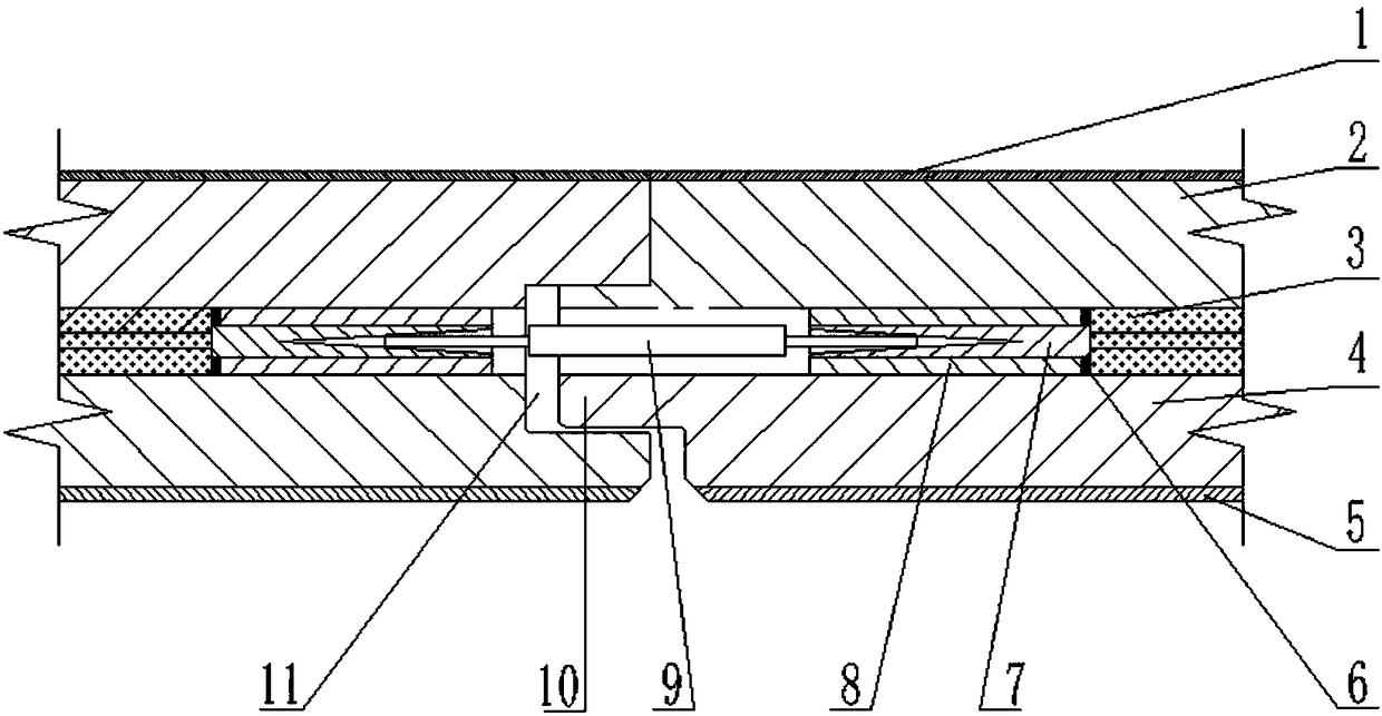
[0025] a. Raw material preparation: Process the decorative surface plate 1, the upper base material 2, the self-limiting temperature heating element 3, the lower base material 4, and the heat insulating material 5 into required sizes, and set up a heating element groove on the upper surface of the lower base material 4, And process the heating element as required, the two ends of the heating element are packaged with the electric connection groove 8 embedded with the copper sleeve 7....

Embodiment

[0038]Firstly, according to the market floor specifications, process the decorative surface plate 1, the upper base material 2, the self-limiting temperature heating element 3, the lower base material 4, and the heat insulation material 5 into required sizes, and process the copper sleeve 7, Electric connection slot 8 and electric conductor 9. Among them, the decorative surface plate 1 is made of Mandshurica mandshurica, with a thickness of 1mm; the upper substrate 2 is a high thermal conductivity formaldehyde-free fiberboard, with a thickness of 6mm; The electric connection groove 8 of the copper sleeve 7; the lower base material 4 is a poplar multi-layer solid wood composite board with a thickness of 8 mm, and the upper surface of the lower base material 4 develops a heating body groove (that is, a longitudinal through groove), and the size is the same as that of the heating element section Dimensions: Heat insulation material 5 is made of aluminum foil heat insulation film ...


PUM

PropertyMeasurementUnit
thermal conductivityaaaaaaaaaa
thicknessaaaaaaaaaa
particle size (mesh)aaaaaaaaaa

Abstract

The invention discloses an electrical heating floor and a preparation method thereof. The electric heating floor is formed by splicing floor units, the floor units include base materials, the base materials are internally provided with self-temperature-limiting heating elements, and electric connecting grooves which are used for arranging electric connecting conductors and communicate with the adjacent self-temperature-limiting heating elements through the electric connecting conductors are inwards formed from the base materials of the splicing positions of the adjacent floor units. The preparation method of the floor comprises the steps that raw materials are prepared, heating element grooves and the electric connecting grooves are formed in the base materials of the floor units, the heating elements are arranged in the heating element grooves, and the electric connecting conductors are inserted into the electric connecting grooves of the adjacent floors so that the floor splicing canbe completed. The self-temperature-limiting heating elements are arranged in the floors, and the output power can be automatically adjusted with the change of temperature so as to ensure safety; andthe adjacent floors are connected by the electric connecting conductors, installation can be carried out without additional tools and is convenient and fast, and the quality is reliable.

Description

technical field [0001] The invention relates to a floor and a preparation method thereof, in particular to an electric heating floor and a preparation method thereof, and belongs to the field of floor heating floor manufacturing. Background technique [0002] The electric heating floor has the advantages of easy room layout, fast heating speed, and uniform temperature distribution. However, there is no mass production in the market at present. The reason is that the existing electric heating floor has a complex structure, cumbersome production process, high cost, high energy consumption, and poor safety. , high installation and post-maintenance costs. Contents of the invention [0003] Purpose of the invention: The first purpose of the present invention is to provide an electric heating floor with simple structure, capable of directional heating and convenient installation and subsequent maintenance; the second purpose of the present invention is to provide a preparation m...

Claims


Application Information

Patent Timeline
Patent Type & Authority Applications(China)
IPC IPC(8): E04F15/02B32B21/02B32B3/06B32B3/08B32B33/00F24D13/02
CPCF24D13/024E04F15/02E04F15/02038B32B3/06B32B3/08B32B21/02B32B33/00E04F2290/023E04F2201/02
Inventor 郦海星
Owner JIANGSU KENTIER WOOD
Why Eureka
Try Eureka