
Infrared radiation film humidifier

An infrared radiation, humidifier technology, applied in air humidification systems, heating methods, lighting and heating equipment, etc., can solve the problems of increasing indoor heating and heating load, polluting ambient air, reducing ambient temperature, etc., and achieving less steam condensation. effect, low evaporation temperature, the effect of improving comfort

Pending Publication Date: 2018-09-07
北京绿能嘉业新能源有限公司
View PDF0 Cites 2 Cited by
  • Summary
  • Abstract
  • Description
  • Claims
  • Application Information

AI Technical Summary

Problems solved by technology

[0005] The above humidification technologies all need to absorb the heat in the environment to form water vapor. During the humidification process, water flies in the air in the form of molecular clusters or particles, which is easy to form a breeding source for bacteria. These tiny water droplets are scattered on dust and objects. , provides breeding conditions for various microorganisms, rapid reproduction when the temperature is suitable, the elderly and children and other frail people are prone to infection after inhalation; clinical medicine is called "humidification pneumonia"; literature records, Yao Chushui's research shows that ultrasonic The water in the humidifier is easy to breed bacteria and pollute the ambient air. As the continuous use time prolongs, the number of bacteria will gradually increase
[0006] In addition, due to the existing humidification technology, the water mist sprayed into the air needs to absorb the sensible heat of the air to be vaporized, which will also cause the ambient temperature to drop and increase the heating load of indoor heating.

Method used


Image

  • Infrared radiation film humidifier
  • Infrared radiation film humidifier
  • Infrared radiation film humidifier

Examples


Embodiment Construction

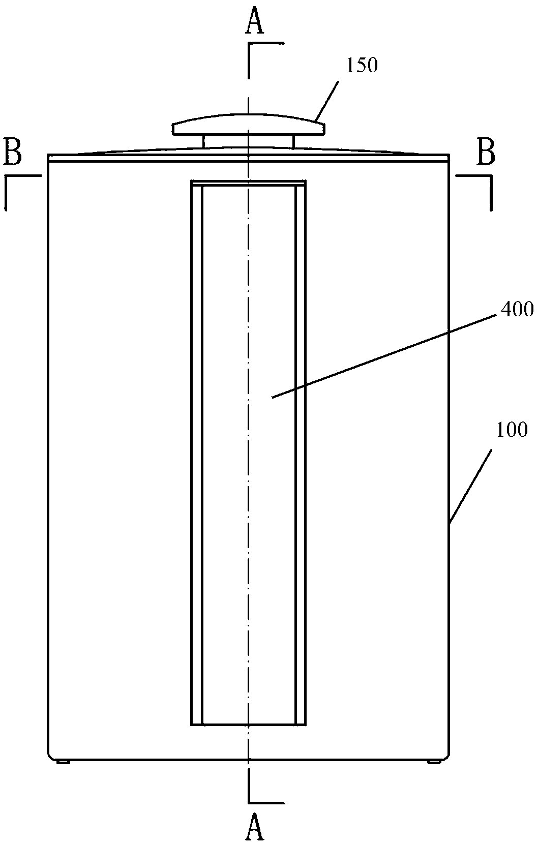
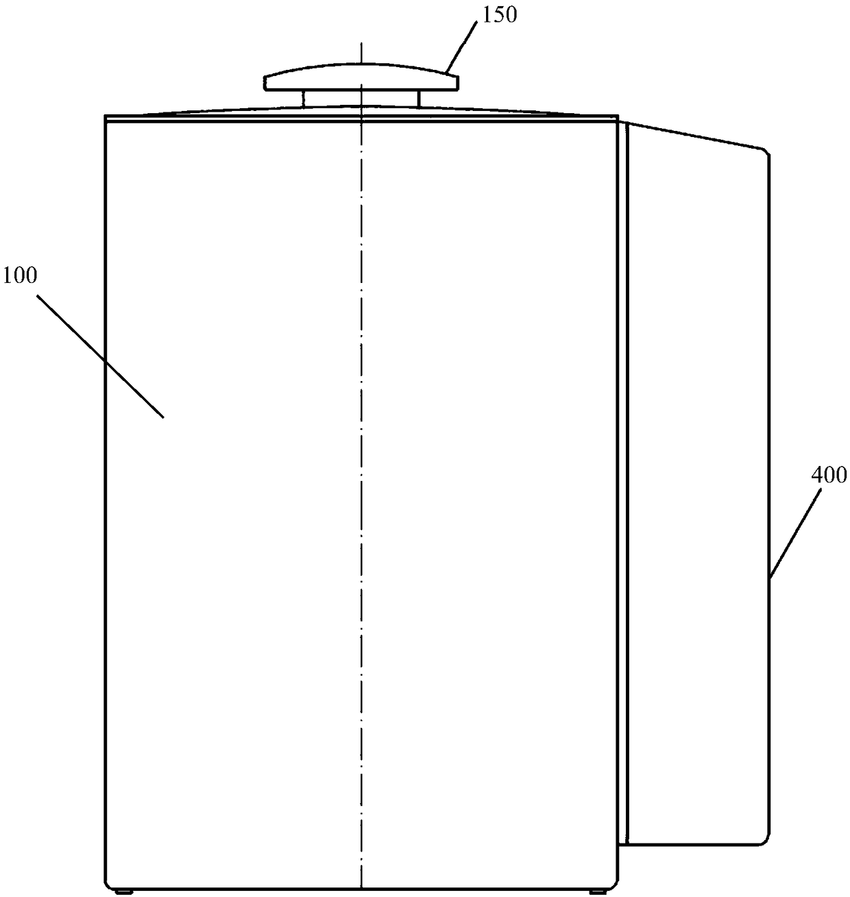
[0033] The infrared radiation film humidifier of the present invention will be described in detail below in conjunction with the accompanying drawings.

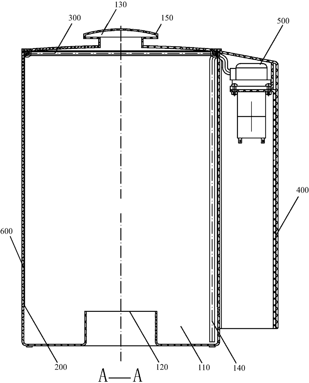
[0034] Such as Figure 1 to Figure 7 As shown, an infrared radiation film humidifier includes an infrared radiation film humidifier, which includes a casing 100, an infrared radiation film 200, an annular micro-flow liquid distribution pipe 300, a protective cover 400 and a micro peristaltic pump 500.

[0035] An accommodating cavity 110 for storing water is provided in the casing 100, so that the casing 100 is formed as a humidifier water tank.

[0036] An air inlet pipe 120 communicating with the containing chamber 110 is provided at the bottom of the casing 100 , and a steam outlet 130 communicating with the containing chamber 110 is provided at the top of the casing 100 .

[0037] Further, a portable cover 150 is also provided on the steam outlet 130 .

[0038] The infrared radiation film 200 is arranged on the cavity w...


PUM


Abstract

The invention relates to an infrared radiation film humidifier. The infrared radiation film humidifier comprises a machine shell, an infrared radiation film, an annular micro flow liquid distributionpipe, a protection cover and a mini peristaltic pump. The mini peristaltic pump is adopted for pumping water in a water pump to the annular micro flow liquid distribution pipe, then water is sprayed and dripped to the infrared radiation film through micro flow needle holes, a thin layer water film is formed on the surface of the infrared radiation film through liquid water, the thin layer water film directly absorbs infrared radiation, after water molecules absorb energy of infrared waves, molecule vibration is directly caused, the water molecules are vaporized along with temperature rise andthen are sprayed out through a steam outlet, and the humidification function is achieved. The infrared radiation film humidifier has the beneficial effect of being capable of saving energy; the problem that tiny water drops fly and pollution is caused, the problem about air cooling and the problem about physiology interference on the human bodies from ultrasonic waves can be solved; forcible waterevaporation can be achieved, evaporation does not depend on water boiling, the evaporation temperature is low, and the steam condensation effect can be reduced; and the temperature rise heat loads caused by condensed steam is avoided for the air conditioner environment.

Description

technical field [0001] The invention relates to a humidifier, in particular to an infrared radiation film humidifier. Background technique [0002] Humidity is one of the main parameters of ambient air, and it is closely related to people's life and production. People live in an environment with a humidity of 40-70%, and they feel comfortable. If the humidity is high, they will feel stuffy, and if the humidity is low, they will feel dry. Long-term exposure to low humidity can also lead to dehydration of the mucous membranes, which can have adverse health effects. If the humidity in the textile industry is lower than 40%, it is easy to break the yarn, and in the tobacco industry, if the humidity is higher than 70%, the cigarettes are prone to mildew. The environmental humidity of microelectronics manufacturing is lower than 30%, which is very easy to generate static electricity, which is extremely unfavorable to product quality and safe production. [0003] The existing hum...

Claims


Application Information

Patent Timeline
IPC IPC(8): F24F6/08F24F6/18
CPCF24F6/08F24F6/18Y02B30/70
Inventor 王敏邓昌沪杨占利陈镇铭
Owner 北京绿能嘉业新能源有限公司
Learn More