

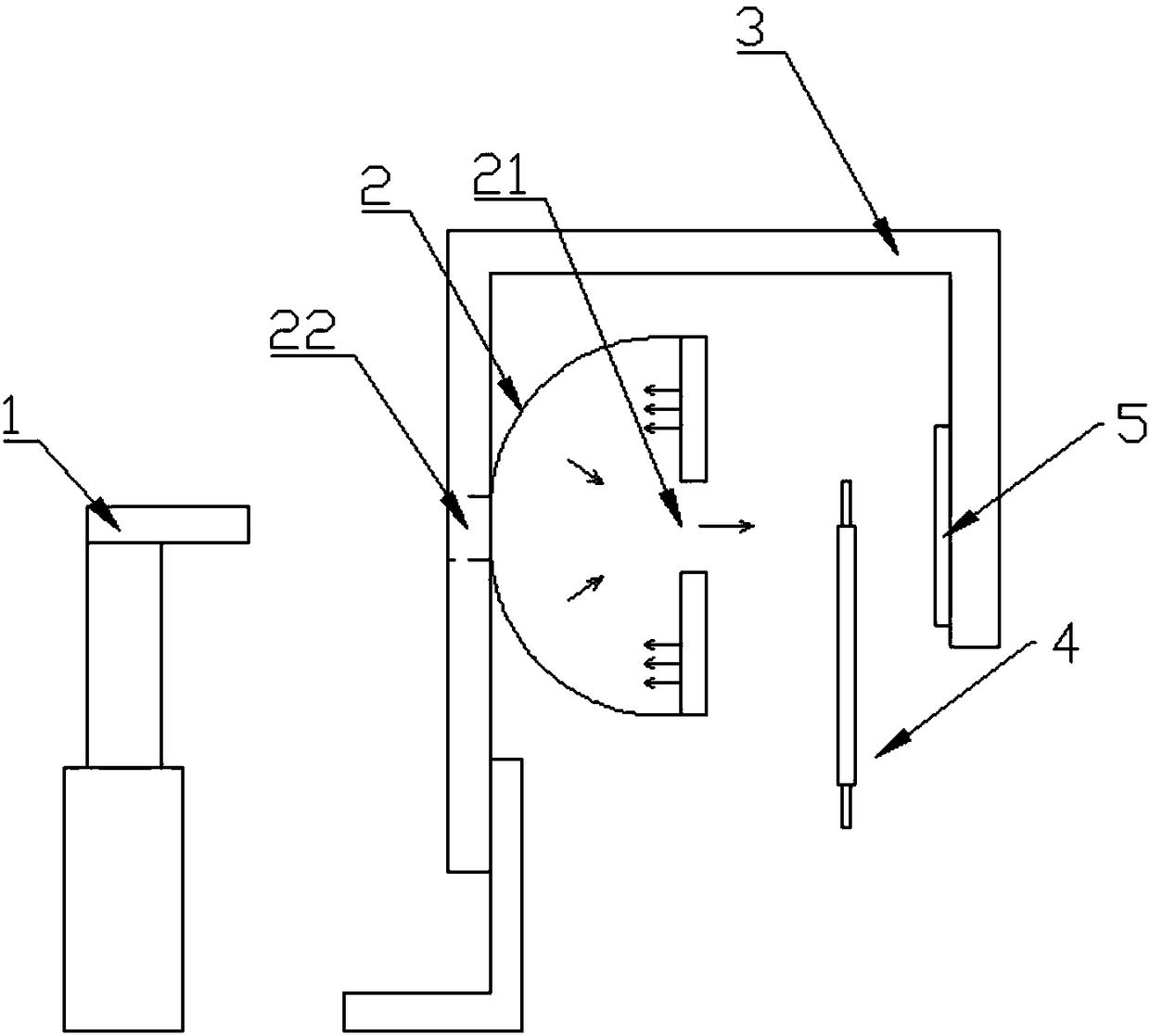
Tab/adhesive tape position detection system and method based on CCD
A detection system and tape technology, applied in the field of lithium battery manufacturing equipment and automation equipment, can solve the problem that the optical fiber cannot realize the detection of the tab/tape, etc., and achieve the effect of good detection effect, simple overall structure and rapid detection.
- Summary
- Abstract
- Description
- Claims
- Application Information
AI Technical Summary
Problems solved by technology
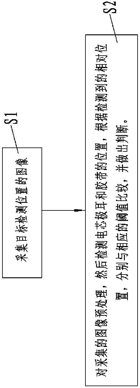
Method used
Image

Examples
Embodiment Construction
[0017] Hereinafter, embodiments of the present invention will be described in detail with reference to the drawings.
[0018] In describing the present invention, it should be understood that the terms "center", "upper", "lower", "front", "rear", "left", "right", "X", "Y", "Z" The orientation or positional relationship indicated by etc. is based on the orientation or positional relationship shown in the drawings, which is only for the convenience of describing the present invention for simplification, and does not indicate or imply that the referred device or element must have a specific orientation, use a specific orientation The structure and operation only represent relative positions, not absolute positions, and should not be construed as limiting the present invention. In addition, the terms "first" and "second" are used for descriptive purposes only, and should not be understood as indicating or implying relative importance.
[0019] In the description of the present in...
PUM
 Abstract
Description
Claims
Application Information