
Product transfer system and method based on planar auxiliary light source and machine vision

An auxiliary light source and machine vision technology, applied in general control systems, control/adjustment systems, instruments, etc., to achieve the effect of avoiding waste of raw materials, solving limitations, and improving product competitiveness

Inactive Publication Date: 2018-09-07
SICHUAN UNIV
View PDF9 Cites 7 Cited by
  • Summary
  • Abstract
  • Description
  • Claims
  • Application Information

AI Technical Summary

Problems solved by technology

[0004] The purpose of the present invention is to overcome the shortcomings of "machine-manual" semi-automation in the prior art, and provide a product transfer system and transfer method based on plane auxiliary light source and machine vision

Method used


Image

  • Product transfer system and method based on planar auxiliary light source and machine vision
  • Product transfer system and method based on planar auxiliary light source and machine vision

Examples


Embodiment 1

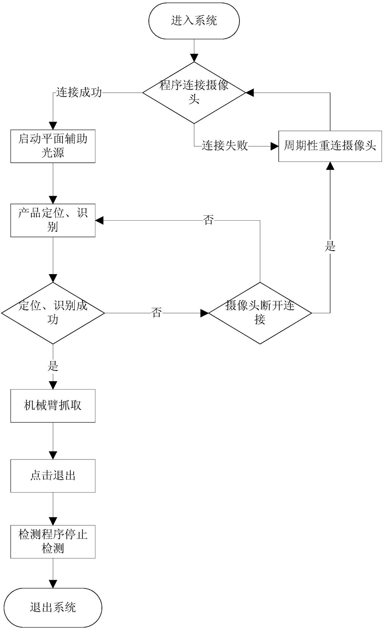
[0044] Such as figure 1 As shown, a product transfer method based on plane auxiliary light source and machine vision, including

[0045] Step 1: Install a plane auxiliary light source around the product to generate a contrast image of the product;

[0046] Step 2: collect contrast images of various types of non-defective standard products as the target image, and the target image is composed of multiple non-defective standard product contrast images using the statistical averaging method;

[0047] Step 3: Collect the angiographic image of the product to be classified on the production platform in real time as the image to be tested;

[0048] Step 4: Identify and match the image to be tested with the target image, confirm each product type, and divide it into standard products and defective products;

[0049] Step 5: Control the robotic arm to classify the products to be classified into standard products and defective products.

[0050] Based on the SURF algorithm, the Hessi...

Embodiment 2

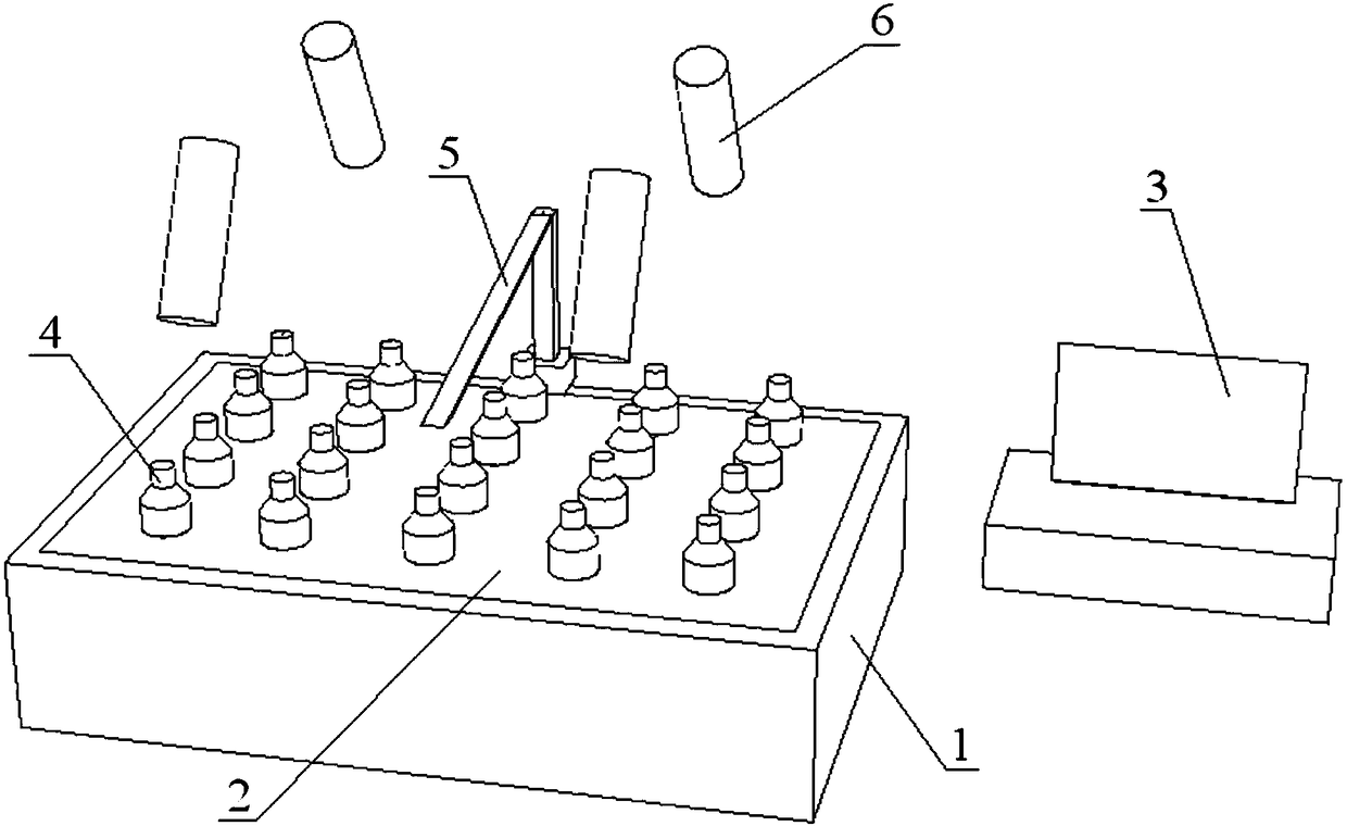
[0059] Such as figure 2 As shown, a product transfer system based on plane auxiliary light source and machine vision includes a backlight 2 arranged at the bottom 1 of the production platform, a camera 6 and a mechanical arm 5 arranged directly above the production platform 1, and the The control module 3 connected to the camera 6 and the mechanical arm 5; the camera 6 collects the contrast image of the product 4 to be classified on the backlight 2, and the control module 3 recognizes the contrast image information and matches it with the target image to confirm After the product type, control the mechanical arm 5 to carry out classification transfer.

[0060] The installation positions of the planar auxiliary light source and the camera of the product transfer system of the present invention can be adjusted according to the actual situation, and all kinds of equipment are common general-purpose equipment with simple structure and convenient installation. The control module ...


PUM


Abstract

The invention discloses a product transfer system and method based on a planar auxiliary light source and machine vision. The transfer method comprises the steps that the planar auxiliary light sourceis installed around products and used for producing contrast images of the products; contrast images of various types of zero-defect standard products are acquired to serve as target images; the contrast images of the products to be classified on a production platform are acquired in real time to serve as images to be detected; the images to be detected and the target images are identified and matched, and the type of each product is determined; a control mechanical arm classifies the products to be classified. The transfer system comprises the planar auxiliary light source installed around products, a camera and the mechanical arm arranged above the production platform, and a control module connected with the camera and the mechanical arm. The camera acquires contrast images of the products on the planar auxiliary light source, the control module identifies contrast image information, matches the information with the target images and controls the mechanical arm to perform classification after the types of the products are confirmed.

Description

technical field [0001] The invention relates to the technical field of packaging automation, in particular to a product transfer system and transfer method based on planar auxiliary light sources and machine vision. Background technique [0002] The scale of domestic filling machine manufacturers is small, and many manufacturers mainly rely on the introduction of foreign technology and production lines, or transform similar products on this basis. The domestic 24-station beverage filling machine has a filling speed of 12000BPH (bottle / hour) for 500ml PET bottles, and a single capping head has a working efficiency of 1500-1800BPH, and the filling capacity error is relatively large, which is different from foreign products. big gap. [0003] At the same time, in order to enhance market competitiveness, wine manufacturers promote wine products of various brands and models at the same time, resulting in diversification of packaging specifications and ununified packaging process...

Claims


Application Information

Patent Timeline
Patent Type & Authority Applications(China)
IPC IPC(8): G05B19/408
CPCG05B19/4086G05B2219/35356
Inventor 张卫华张意周琳琳刘哲黄悦凯李涛
Owner SICHUAN UNIV
Learn More