Switch cabinet convenient to assemble and disassemble

A technology that is convenient for installation and switchgear, and is applied in the direction of panel/switch station circuit devices, substation/switch layout details, substation/switch device cooling/ventilation, etc., which can solve unsatisfactory energy-saving effects, inconvenient installation and disassembly, heat dissipation and ventilation To improve the heat dissipation and ventilation effect, facilitate installation and disassembly, and avoid safety hazards

Active Publication Date: 2018-09-07
江西明正智能电气有限公司
View PDF6 Cites 2 Cited by
  • Summary
  • Abstract
  • Description
  • Claims
  • Application Information

AI Technical Summary

Problems solved by technology

[0002] High and low voltage switchgear is suitable for power plants, petroleum, chemical industry, metallurgy, textiles, high-rise buildings and other industries. It is used for power transmission, power distribution and power conversion. It has high use value and is currently used in my country. Wide, but most of the traditional high and low voltage switchgears are large in size, which makes it extremely inconvenient to install and disassemble them, and when used outdoors, they cannot adapt to the influence of rain, snow and other weather, the heat dissipation and ventilation are not good, and the current Some control cabinets have poor dust-proof effect, weak earthquake resistance, unsatisfactory energy-saving effect, and cannot monitor the temperature and humidity in the cabinet in real time. In addition, due to the wide distribution of switch cabinets and the large number, when a certain switch cabinet fails , unable to quickly find the location of the switchgear

Method used


Image

  • Switch cabinet convenient to assemble and disassemble
  • Switch cabinet convenient to assemble and disassemble
  • Switch cabinet convenient to assemble and disassemble

Examples


Embodiment Construction

[0027] In order to make the purpose, technical solution and advantages of the present invention clearer, the technical solution of the present invention will be described in detail below. Apparently, the described embodiments are only some of the embodiments of the present invention, but not all of them. Based on the embodiments of the present invention, all other implementations obtained by persons of ordinary skill in the art without making creative efforts fall within the protection scope of the present invention.

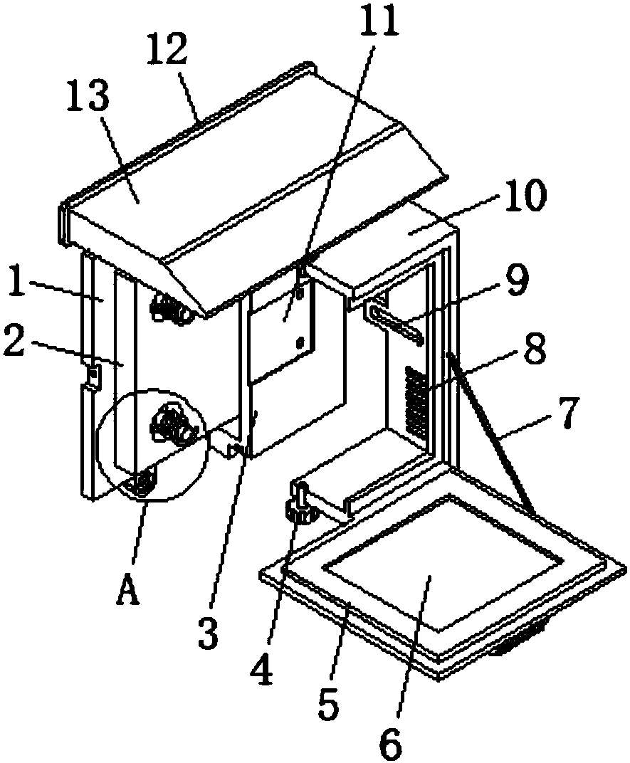
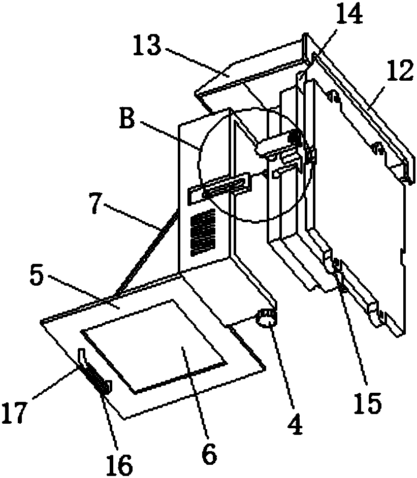
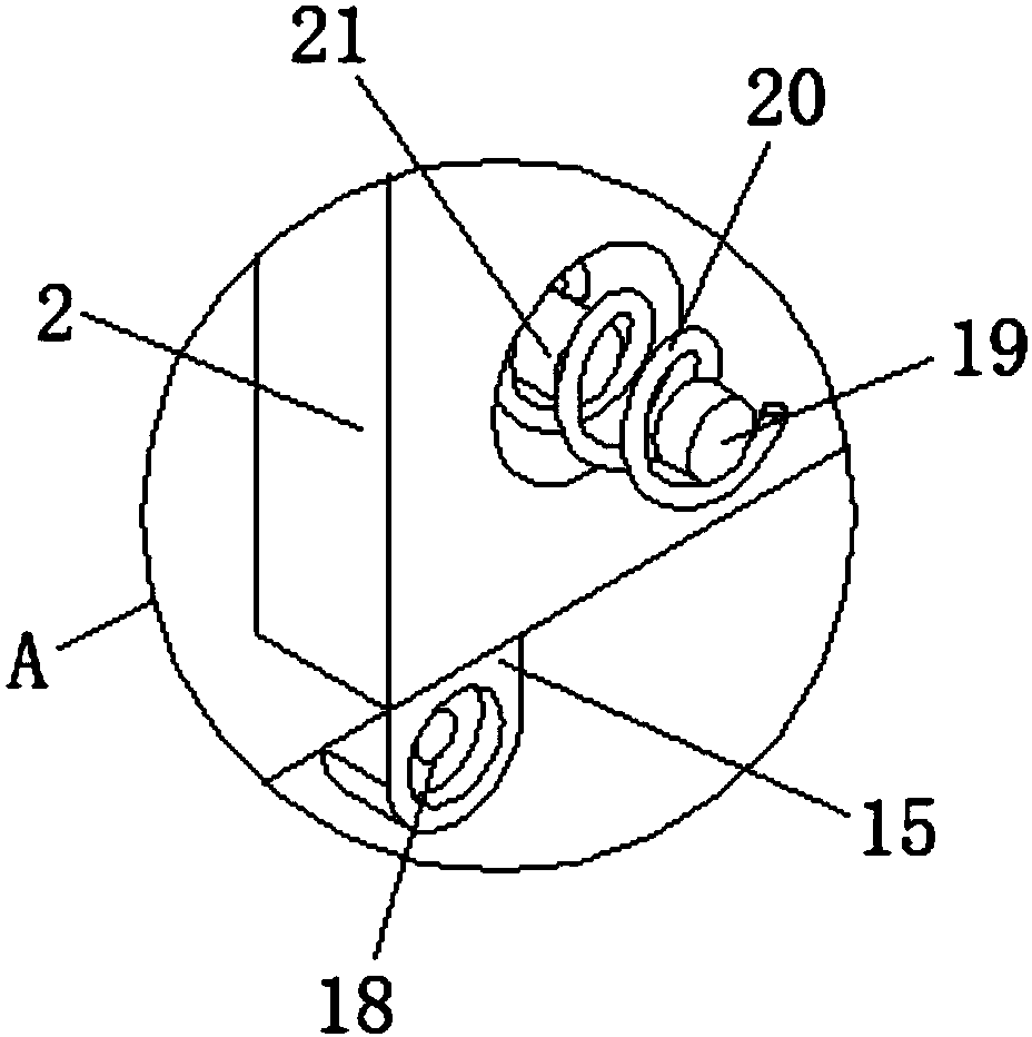
[0028] see Figure 1-Figure 4 As shown, the present invention provides a switchgear that is easy to install and disassemble, including a fixed plate 1, a slide table 2 is provided on one side of the fixed plate 1, and a connecting boss 3 is provided on the side of the slide table 2 away from the fixed plate 1, The connecting boss 3 is connected with the sliding table 2 through the rectangular chute provided inside, and the side of the connecting boss 3 away fro...


PUM


Abstract

The invention discloses a switch cabinet convenient to assemble and disassemble. The switch cabinet comprises a fixing plate, wherein a sliding table is arranged on one side of the fixing plate; a connection boss is arranged on one side, far away from the fixing plate, of the sliding table; the connection boss is connected with the sliding table via a rectangular sliding chute formed in the connection boss; a switch protective cover shell is connected with one side, far away from the sliding table, of the connection boss via a fastening bolt; a turn cover is connected with one side of the switch protective cover shell via a hinge; one end of a pull cord is connected with one side of the turn cover, the switch protective cover shell and the connection boss are installed and connected via the fastening bolt, and an installation hole is formed in the middle of the inner part of the installation plate, so that the switch cabinet can be conveniently assembled and disassembled; when is in outdoor use, the switch cabinet can adapt to influences of rainy and snowy weather via the cooperated use of a sealing leakproof cushion and a rain baffle, the heat dissipation and ventilation effect can be greatly improved via a ventilating slot, and the seismic resistance of the switch can be improved by a damping spring arranged between the sliding table and the connection boss.

Description

technical field [0001] The invention relates to the field of switchgear equipment, in particular to a switchgear that is convenient for installation and disassembly. Background technique [0002] High and low voltage switchgear is suitable for power plants, petroleum, chemical industry, metallurgy, textiles, high-rise buildings and other industries. It is used for power transmission, power distribution and power conversion. It has high use value, and it is currently used in our country. Wide, but most of the traditional high and low voltage switch cabinets are large in size, which makes it extremely inconvenient to install and disassemble them, and when used outdoors, they cannot adapt to the influence of rain, snow and other weather, the heat dissipation and ventilation are not good, and the current Some control cabinets have poor dust-proof effect, weak earthquake resistance, unsatisfactory energy-saving effect, and cannot monitor the temperature and humidity in the cabine...

Claims


Application Information

Patent Timeline
Patent Type & Authority Applications(China)
IPC IPC(8): H02B1/30H02B1/28H02B1/56H02B1/54H02B1/24H02B1/32
CPCH02B1/24H02B1/28H02B1/30H02B1/306H02B1/32H02B1/54H02B1/565
Inventor 来素霞
Owner 江西明正智能电气有限公司
Why Eureka
Try Eureka