Hinge beam assembly and novel synthesis press
A technology of hinge beam and assembly, applied in the field of hinge beam assembly and new synthetic press, can solve problems such as poor synchronization accuracy, affect efficiency, affect synchronization accuracy, etc., and achieve simplification of control system, high precision and reliability, High reliability effect
- Summary
- Abstract
- Description
- Claims
- Application Information
AI Technical Summary
Problems solved by technology
Method used
Image
Examples
Embodiment 1
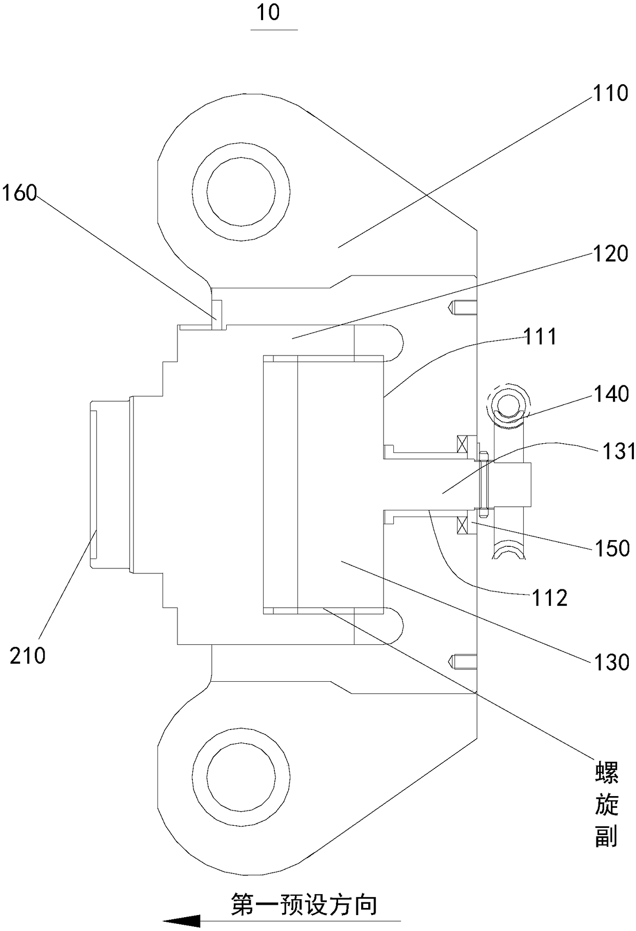
[0078] Please refer to figure 1 , figure 1 It is a schematic structural diagram of a hinged beam assembly 10 provided by an embodiment of the present invention. from figure 1 A hinge beam assembly 10 can be seen in , which includes a main body 110 , a thrust column 120 , a threaded body 130 and a driving device 140 .
[0079] The thrust column 120 is movably arranged on the main body 110 along the first preset direction; a transmission connection is formed between the driving device 140 and the threaded body 130; the thrust column 120 is threadedly connected with the threaded body 130, and the driving device 140 is configured to drive the threaded body 130 drives the thrust column 120 to reciprocate along a first preset direction; the main body 110 carries the movement of the thrust column 120 through the threaded body 130 .
[0080] In this embodiment of the present invention, the threaded body 130 is threadedly connected with the thrust column 120, and the thrust column 1...
Embodiment 2
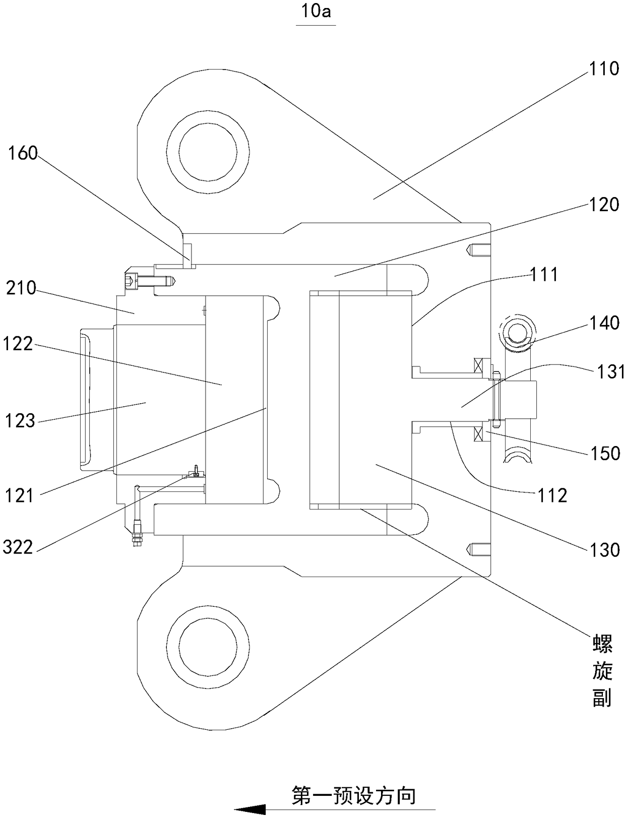
[0090] Please refer to figure 2 , figure 2 A schematic diagram of the structure of the hinge beam assembly 10a provided by this embodiment of the present invention. from figure 2It can be seen from the figure that such a hinged beam assembly 10a is substantially the same as the hinged beam assembly 10a in Embodiment 1, except that the thrust column 120 also includes an ultra-high pressure cylinder 121, a piston 122, a piston rod 123 and a guide sleeve 210 .
[0091] Further, the guide sleeve 210 is arranged between the piston rod 123 and the ultra-high pressure cylinder 121; the piston 122 is movably arranged in the ultra-high pressure cylinder 121 through the piston rod 123; and the piston 122 is configured to be arranged at one end of the thrust column 120 .
[0092] In this embodiment, there is a guide sleeve 210 between the ultra-high pressure cylinder 121 and the piston rod 123 ; there is also a first guide key 160 between the guide sleeve 210 and the piston rod 12...
Embodiment 3
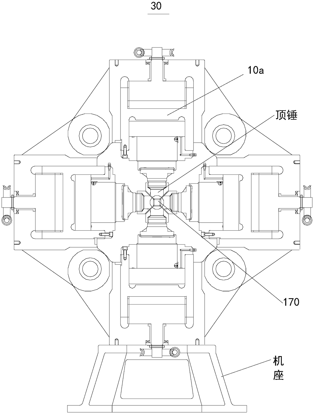
[0116] Figure 4 The novel composite press 20 provided for the present embodiment of the present invention; Figure 5 for Figure 4 Schematic diagram of another view of the structure. from Figure 4 and Figure 5 As can be seen in , a novel composite press 20 includes six hinged beam assemblies hinged to each other.
[0117] Among them, four hinge beam assemblies located on the same plane constitute a passive bearing hinge beam assembly 21, and the remaining two hinge beam assemblies constitute an active pressurization hinge beam assembly 22;
[0118] The hinge beam assembly passively carrying the hinge beam assembly 21 is the hinge beam assembly 10 in Embodiment 1;
[0119]In this embodiment, the hinge beam assembly of the actively pressurized hinge beam assembly 22 is the hinge beam assembly 10a in the second embodiment.
[0120] The thrust column 120 of the active pressurized hinge beam assembly 22 includes an ultra-high pressure cylinder 121, a piston 122, a piston 1...
PUM
| Property | Measurement | Unit |
|---|---|---|
| Thrust | aaaaa | aaaaa |
Abstract
Description
Claims
Application Information
 - R&D
- Intellectual Property
- Life Sciences
- Materials
- Tech Scout
- Unparalleled Data Quality
- Higher Quality Content
- 60% Fewer Hallucinations
Browse by: Latest US Patents, China's latest patents, Technical Efficacy Thesaurus, Application Domain, Technology Topic, Popular Technical Reports.
© 2025 PatSnap. All rights reserved.Legal|Privacy policy|Modern Slavery Act Transparency Statement|Sitemap|About US| Contact US: help@patsnap.com


