Volume high-pressure water pump with slide block structure

A high-pressure water pump, positive displacement technology, applied in rotary piston pumps, rotary piston/swing piston pump components, pumps, etc., can solve the problems of short service life, large vibration of positive displacement pumps, low lift, etc. The effect of volume and weight, improved work efficiency, and convenient mobile use

Pending Publication Date: 2018-09-14
马明
View PDF0 Cites 2 Cited by
  • Summary
  • Abstract
  • Description
  • Claims
  • Application Information

AI Technical Summary

Problems solved by technology

At this time, the compressed liquid exceeds the hydraulic pressure outside the outlet, and the liquid flows out from the outlet, and the continuous operation of the pump achieves the purpose of continuous pumping; since the water supply to high-rise buildings in cities is almost used for a long time, the positive displacement pump needs to be repaired or replaced frequently at present. There are five problems: 1. The rotor is installed with a bearing structure, and the bearing is easily corroded by water, which makes the overall service life of the positive displacement pump shorter; 2. The rotor is eccentrically rotated, which affects the service life of the pump; Erosion and short service life; 4. When the displacement pump is running, there will be pulse force due to the high pressure water pumping, which will cause the displacement pump to vibrate very large, and it is necessary to install an airbag damper to operate normally, which increases the cost; 5. Due to the high pressure of the displacement pump The side leakage cannot be effectively solved during operation, resulting in low head

Method used


Image

  • Volume high-pressure water pump with slide block structure
  • Volume high-pressure water pump with slide block structure
  • Volume high-pressure water pump with slide block structure

Examples


Embodiment Construction

[0043] In order to make the object and technical solutions of the present invention clearer, the present invention will be further described below in conjunction with the accompanying drawings and embodiments:

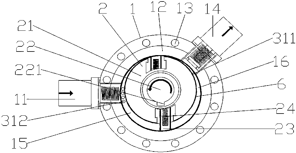
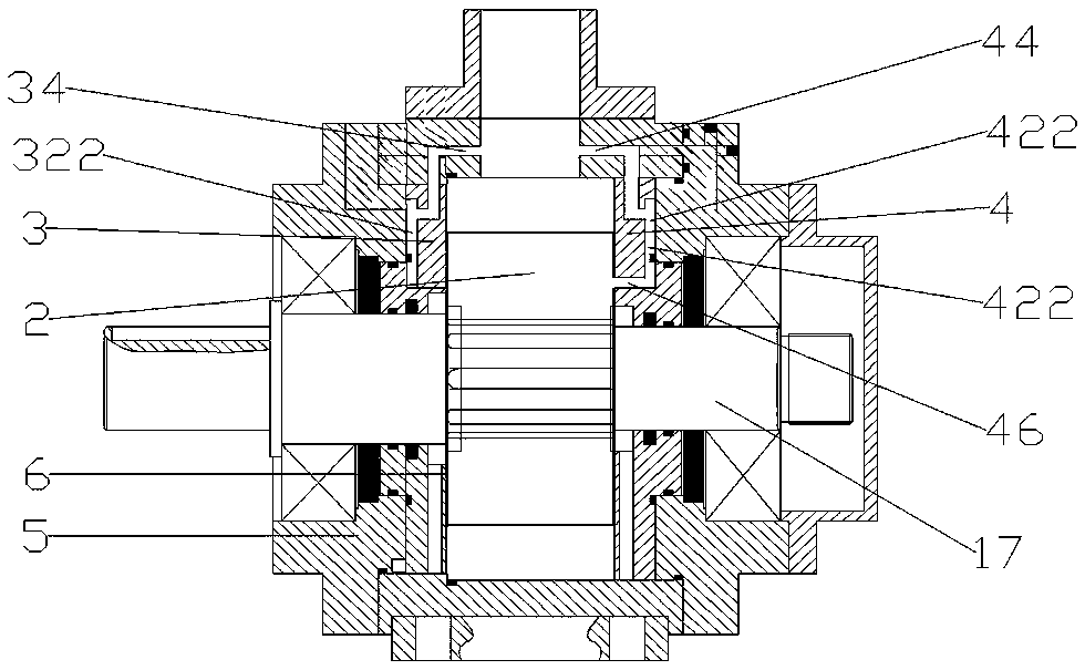
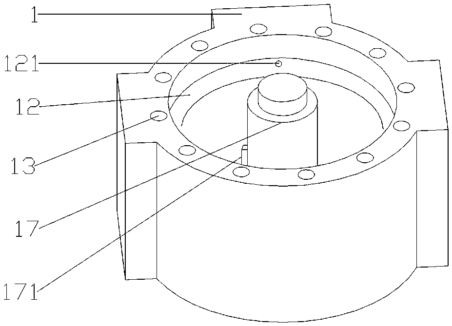
[0044] Such as Figure 1 to Figure 9 A volumetric high-pressure water pump with a slider structure shown includes a pump main body 1, a rotor 2, a left side plate 3, a right side plate 4, and an end cover 5. The pump main body 1 is provided with a water inlet 11, a stator 12, and an outlet. The water port 14, the drive shaft 17; the stator 12 is fixed inside the pump main body 1, and two inner pin holes 121 for installing the left side plate 3 and the right side plate 4 are respectively provided on both sides of the stator 12; the water inlet 1 and the outlet The water ports 14 are staggered and installed on the pump body, and the center line of the water inlet 11 and the center line of the water outlet 14 intersect at the center of the pump body, and the intersection ...


PUM


Abstract

The invention provides a volume high-pressure water pump with a slide block structure. The volume high-pressure water pump with the slide block structure comprises a pump main body, a rotor, a left side plate, a right side plate and end covers. The volume high-pressure water pump with the slide block structure is characterized in that the pump main body is provided with a water inlet, a stator, awater outlet and a transmission shaft; the stator is fixedly arranged in the pump main body; a left side plate is mounted on the left side of the stator through a side plate movable mounting device; the left side plate is provided with a left side plate inner side surface and a left side plate outer side surface; a right side plate is mounted on the right side of the stator through the side platemovable mounting device; the right side plate is provided with a right side plate inner side surface and a right side plate outer side surface; the end covers are arranged on the outer side of the left side plate and the outer side of the right side plate; and the end covers are fixed on the pump main body through end cover connecting devices. As a rotor makes a peripheral motion, a bearing in therotor can be canceled to prevent shortening of the service life of the water pump due to water erosion of the bearing in the rotor.

Description

technical field [0001] The invention relates to a volumetric high-pressure water pump with a slider structure. Background technique [0002] At present, domestic water and fire-fighting water are supplied by water pumps, but the traditional centrifugal water pumps can no longer meet the needs of the times; because the floors are getting higher and higher, and the pressure of fire-fighting water is increasing, centrifugal water pumps can only be Relay water supply, so the positive displacement pump appeared; the positive displacement pump refers to a machine that can change the volume of the space and operate continuously in a closed space at the same time. The crescent-shaped space is divided into three parts A, B, and C. When the rotor rotates in one direction, the volume of the space A communicating with the water inlet increases gradually, and it is in the process of water intake. And the volume of the space C communicating with the water outlet is gradually shrinking, j...

Claims


Application Information

Patent Timeline
Patent Type & Authority Applications(China)
IPC IPC(8): F04C2/344F04C15/00F04C15/06
CPCF04C2/3445F04C15/00F04C15/0023F04C15/062F04C2220/40F04C2240/20F04C2280/04
Inventor 马明刘显华
Owner 马明
Why Eureka
Try Eureka