Heat exchange core for two-way inlet/outlet air hose
A heat exchange core, air in and out technology, applied in the field of air conditioning, can solve the problems of large space occupation and high renovation cost
- Summary
- Abstract
- Description
- Claims
- Application Information
AI Technical Summary
Problems solved by technology
Method used
Image
Examples
Embodiment 1
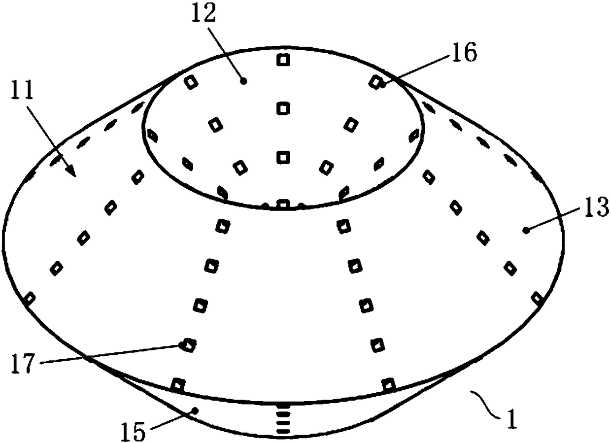
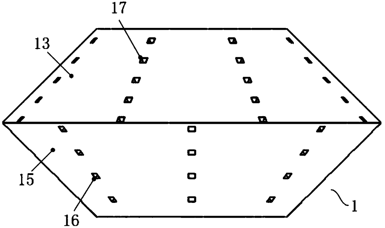
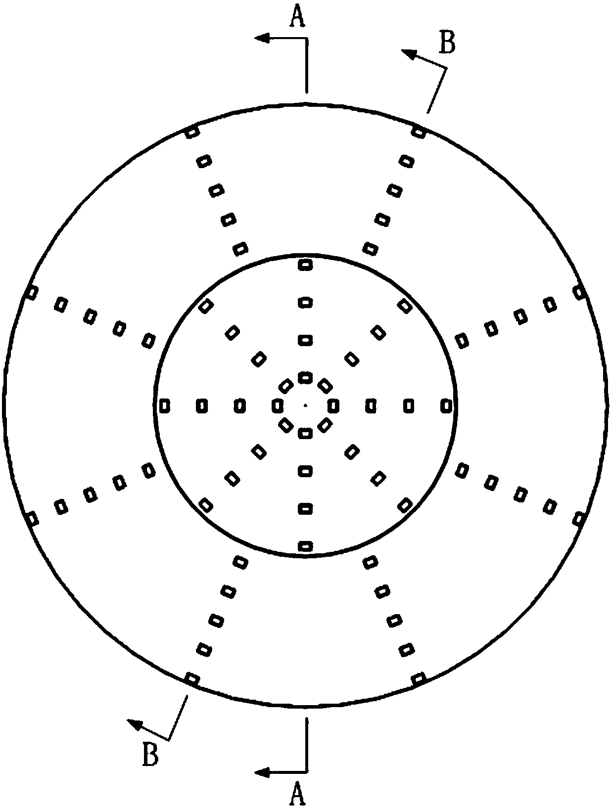
[0043] First refer to Figure 1 to Figure 6 , to describe the first embodiment of the heat exchange core used in the two-way inlet and outlet air ducts of the present invention. in, figure 1 It is a structural schematic diagram of the heat exchange core used for the two-way inlet and outlet air ducts in the first embodiment of the present invention; figure 2 It is the front view of the heat exchange core used for the two-way inlet and outlet air ducts in the first embodiment of the present invention; image 3 It is a top view of the heat exchange core used for the two-way inlet and outlet air ducts in the first embodiment of the present invention; Figure 4 for image 3 Sectional view along A-A direction; Figure 5 for image 3 Sectional view along B-B direction; Figure 6 It is a structural schematic diagram of the heat exchanger in the first embodiment of the present invention.
[0044] Such as Figure 1 to Figure 6 As shown, the present invention firstly provides a...
Embodiment 2
[0053] Refer below Figure 8 to Figure 12 , to describe the second embodiment of the heat exchange core used in the two-way inlet and outlet air ducts of the present invention. in, Figure 8 It is a structural schematic diagram of the heat exchange core used for the two-way inlet and outlet air ducts in the second embodiment of the present invention; Figure 9 It is the front view of the heat exchange core used for the two-way inlet and outlet air ducts in the second embodiment of the present invention; Figure 10 for Figure 9 Sectional view along C-C direction; Figure 11 for Figure 9 Sectional view along D-D direction; Figure 12 It is a structural schematic diagram of the heat exchanger in the second embodiment of the present invention.
[0054] Such as Figure 8 to Figure 12 As shown, the present invention also provides a heat exchange core 3 for a two-way inlet and outlet air duct 4, the two-way inlet and outlet air duct 4 includes an outer tube 41 and a first in...
Embodiment 3
[0061] Refer below Figure 13 to Figure 16 , the dual-flow fresh air purification device of the present invention is described. in, Figure 13 It is a structural schematic diagram (without draft tube) of the dual-flow fresh air purification device of the present invention; Figure 14 It is a schematic diagram of the working principle of the dual-flow fresh air purification device of the present invention (without draft tube); Figure 15 It is a schematic structural view of the dual-flow fresh air purification device of the present invention (there is a draft tube); Figure 16 It is a schematic diagram of the working principle of the dual-flow fresh air purification device of the present invention (with a draft tube).
[0062] Such as Figure 13 and Figure 14 As shown, the dual-flow fresh air purification device 5 of the present invention (hereinafter referred to as the purification device 5) mainly includes a two-way air inlet and outlet duct, an air intake system and an...
PUM
 Abstract
Description
Claims
Application Information
 - R&D
- Intellectual Property
- Life Sciences
- Materials
- Tech Scout
- Unparalleled Data Quality
- Higher Quality Content
- 60% Fewer Hallucinations
Browse by: Latest US Patents, China's latest patents, Technical Efficacy Thesaurus, Application Domain, Technology Topic, Popular Technical Reports.
© 2025 PatSnap. All rights reserved.Legal|Privacy policy|Modern Slavery Act Transparency Statement|Sitemap|About US| Contact US: help@patsnap.com


