Drying system

A drying system and drying chamber technology, which can be used in drying gas arrangement, local stirring dryer, static material dryer, etc., can solve problems such as increasing system operation energy consumption and time, inconsistent material drying progress, and large drying chamber resistance. , to achieve the effect of maximizing heat utilization, synchronizing effective drying, and maximizing dehumidification

Active Publication Date: 2018-09-14
NANHUA UNIV
View PDF11 Cites 1 Cited by
  • Summary
  • Abstract
  • Description
  • Claims
  • Application Information

AI Technical Summary

Problems solved by technology

In the actual operation process, due to the limitation of the structure design of the existing heat pump drying equipment, the inlet and outlet of the air circulation into and out of the drying chamber are usually a single square or round mouth, and the dry and hot air enters the drying chamber and diffuses, and the cold and wet air is in the drying chamber. The room is shrunk and then discharged. In this way, the resistance of air entering and leaving the drying room is very large, resulting in uneven air speed and air volume in the drying room, especially the four corners of the drying room are often dead corners of ventilation, resulting in the drying progress of materials in different areas of the drying room. Inconsistency greatly affects the drying quality of materials and increases the energy consumption and time of system operation

Method used


Image

  • Drying system
  • Drying system
  • Drying system

Examples


Embodiment 1

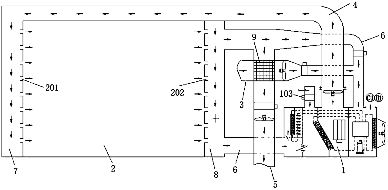
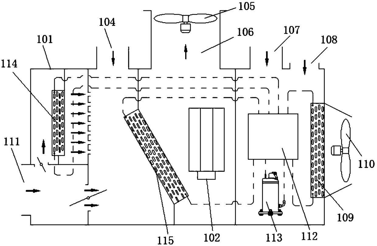
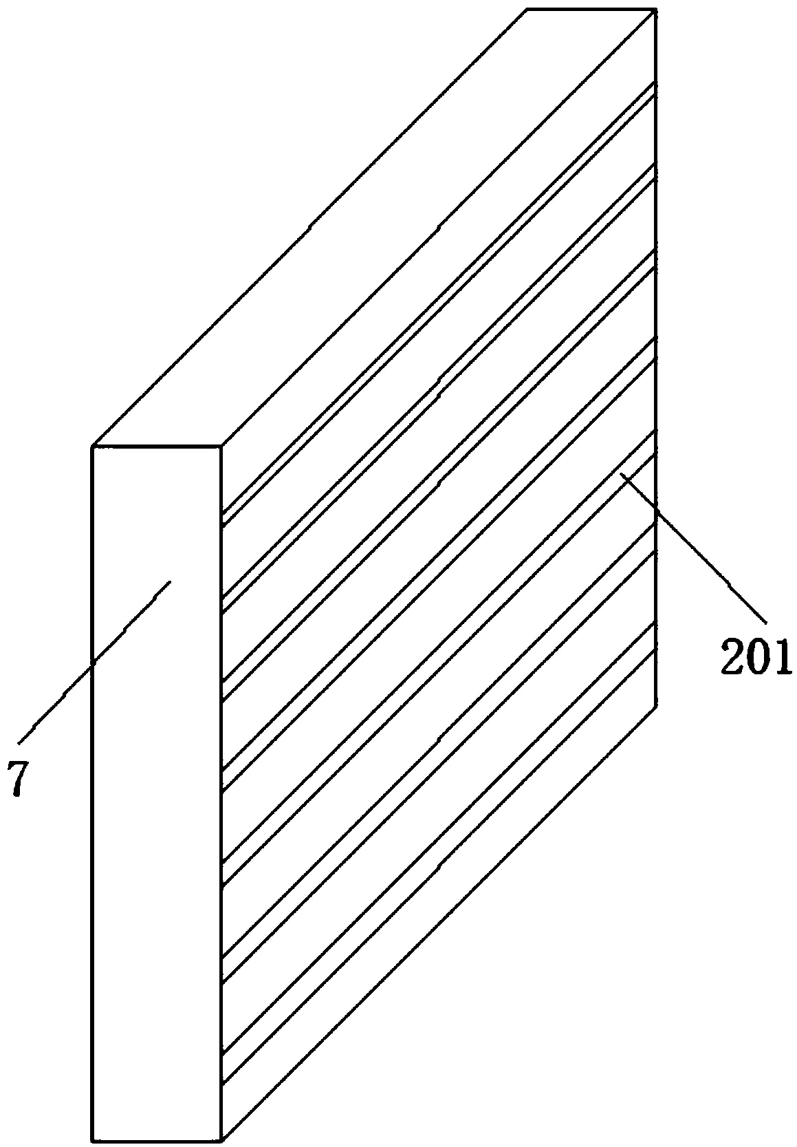
[0032] see Figure 1 to Figure 4 , Figure 1 to Figure 4 A specific embodiment of a drying system of the present invention is provided, wherein, figure 1 It is a schematic diagram of the overall structure of the drying system disclosed in Embodiment 1 of the present invention; figure 2 It is a structural schematic diagram of the heat pump unit disclosed in Embodiment 1 of the present invention; image 3 It is a schematic structural diagram of the air supply chamber disclosed in Embodiment 1 of the present invention; Figure 4 It is a schematic structural diagram of the return air chamber disclosed in Embodiment 1 of the present invention.

[0033] Such as Figure 1 to Figure 4 As shown, the drying system provided by the present invention can realize the simultaneous drying of materials in different areas of the drying chamber, greatly optimize the drying quality of materials, and reduce the energy consumption and time of system operation. The drying system includes a hea...

Embodiment 2

[0060] see Figure 5 to Figure 8 , Figure 5 to Figure 8 Another specific embodiment of a drying system of the present invention is provided, wherein, Figure 5 It is a schematic diagram of the connection of the pipe valve assembly in the return air heating state disclosed in Embodiment 2 of the present invention; Figure 6 It is a schematic diagram of the connection of the pipe valve assembly in the return air heating and dehumidification state disclosed in Embodiment 2 of the present invention; Figure 7 It is a schematic diagram of the connection of the pipe valve assembly under the high-temperature return air refrigeration state disclosed in Embodiment 2 of the present invention; Figure 8 It is a schematic diagram of the connection of the pipe valve assembly in the return air low-temperature refrigeration state disclosed in Embodiment 2 of the present invention;

[0061] Such as Figure 5 to Figure 8As shown, the pipe valve assembly provided in this embodiment include...

Embodiment 3

[0117] see Figure 9 , Figure 9 Another specific embodiment of the present invention is provided, wherein, Figure 9 It is a schematic diagram of the overall structure of the drying system disclosed in Example 3 of the present invention.

[0118] In this embodiment, the air outlets 201 are evenly distributed on the upper side wall of the drying chamber 2 from left to right, and the air outlets 202 are evenly distributed on the lower side wall of the drying chamber 2 from left to right.

[0119] In this embodiment, the air blower 105 is connected to the vertically arranged air supply chamber (adjusted from the horizontally arranged air supply chamber in Embodiment 1 to a vertical air supply chamber) through the air supply pipe 4, and the vertical air supply port of the air supply chamber is arranged vertically 201 communicates with the drying chamber 2, the air outlet 202 communicates with the drying chamber 2, and finally can be connected with the main return air outlet of ...


PUM


Abstract

The invention discloses a drying system which comprises a heat pump unit and a drying room, wherein a cold air pipe for importing cold air and a blowing pipe for exporting hot air are arranged on theheat pump unit; blowing openings are fully distributed in the side wall of one side of the drying room; air outlets are fully distributed in the wall of the other opposite side of the drying room; theblowing pipe is connected to the blowing openings; the air outlets communicate to a first exhaust pipe and a second exhaust pipe; the first exhaust pipe is connected to the outer side and the secondexhaust pipe is connected to the heat pump unit. The drying system can dry materials in different regions in the drying room synchronously smoothly through the structural design, so that the drying quality of the materials is optimized extremely, and the energy consumption and the time of system operation are reduced.

Description

technical field [0001] The present invention relates to the field of drying equipment, and more specifically relates to a drying system. Background technique [0002] Drying generally refers to various operations that remove water or other moisture from wet materials. For example: In daily life, wet materials are exposed to sunlight to remove moisture; in industry, silica gel, lime, concentrated sulfuric acid, etc. are used to remove moisture in air, industrial gases or organic liquids; in chemical production, heat and mass transfer is relied on, and hot air is used , flue gas and infrared rays to heat the wet solid material, so that the moisture or solvent contained in it is vaporized and removed. The purpose of drying is to make materials convenient for storage, transportation and use, or to meet the needs of further processing. For example, grains and vegetables can be stored for a long time after drying; synthetic resin can prevent air bubbles or moiré in plastic produ...

Claims


Application Information

Patent Timeline
Patent Type & Authority Applications(China)
IPC IPC(8): F26B9/06F26B21/02F26B23/00
CPCF26B9/06F26B21/001F26B21/02F26B23/00
Inventor 向立平王汉青黄坤荣
Owner NANHUA UNIV
Why Eureka
Try Eureka