Nb oxide based gating device and preparation method thereof
A technology for gating devices and oxides, applied in electrical components and other directions, and can solve problems such as poor stability
- Summary
- Abstract
- Description
- Claims
- Application Information
AI Technical Summary
Problems solved by technology
Method used
Image

Examples
preparation example Construction
[0031] The present invention also provides a method for preparing a gate device based on niobium oxide described in the above technical solution, comprising the following steps:
[0032] (1) Using argon as the working gas and using the niobium pentoxide target as the sputtering target, the first sputtering is performed on the surface of the bottom electrode to obtain a semi-finished gate device based on niobium oxide;
[0033] (2) Argon is used as the working gas, and the platinum target is used as the sputtering target, and the second sputtering is carried out on the surface of the niobium oxide of the gate device semi-finished product based on the oxide of niobium to obtain the oxide based on niobium. gating device.
[0034] In the present invention, a platinum target and a niobium pentoxide target are preferably installed on the magnetron sputtering equipment, and then after the vacuum chamber of the magnetron sputtering equipment is evacuated, argon gas is introduced to th...
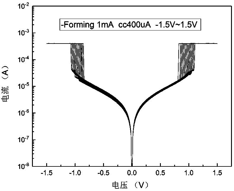
Embodiment 1
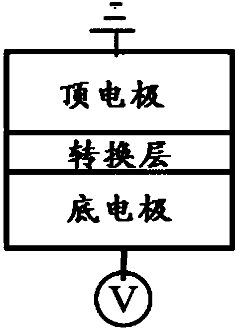
[0051] (1) will have an area of 1μm 2 The surface of the mold-loading base material of the TiN bottom electrode is washed by high-pressure air, and it is used for standby; the TiN bottom electrode is square and has a thickness of 200nm;
[0052] (2) Install a platinum target and a niobium pentoxide target in the magnetron sputtering equipment, place the mold carrier substrate with the TiN bottom electrode obtained in step (1) in the magnetron sputtering equipment, and place the vacuum chamber After evacuating, argon is introduced until the system pressure is 4 Torr;
[0053] (3) Turn on the radio frequency measurement and control sputtering power supply, and at a temperature of 300K, with a power of 120W, sputter niobium pentoxide to the surface of the TiN bottom electrode for 800s, then turn off the radio frequency magnetron sputtering to obtain a semi-finished product;
[0054] (4) Turn on the DC magnetron sputtering power supply, and at a temperature of 300K, with a powe...
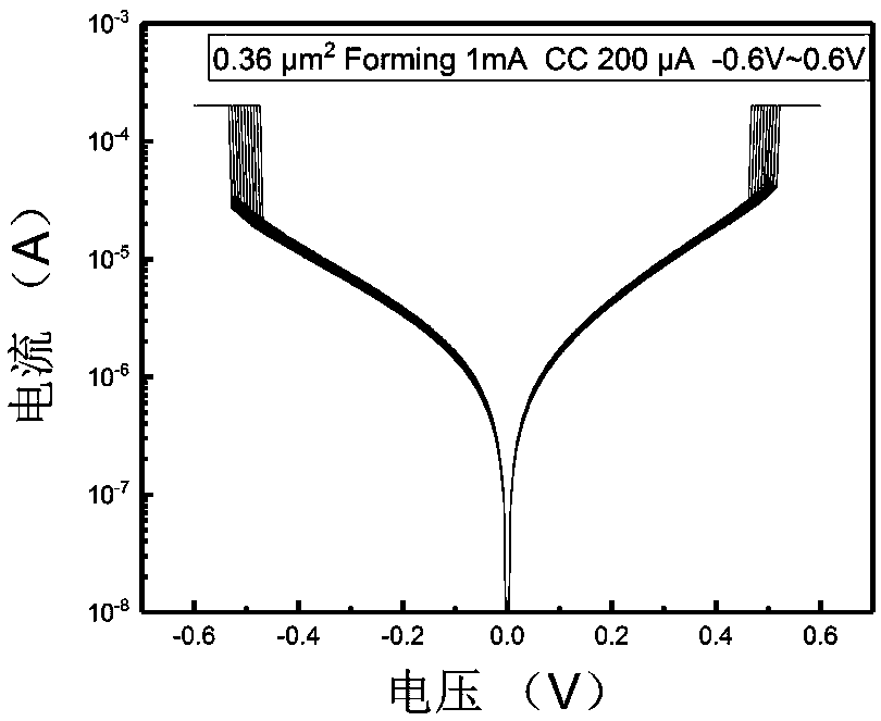
Embodiment 2
[0059] (1) will have an area of 0.36μm 2 The surface of the mold-loading base material of the TiN bottom electrode is washed by high-pressure air, and it is used for standby; the TiN bottom electrode is square and has a thickness of 200nm;
[0060] (2) Install a platinum target and a niobium pentoxide target in the magnetron sputtering equipment, place the mold carrier substrate with the TiN bottom electrode obtained in step (1) in the magnetron sputtering equipment, and place the vacuum chamber After evacuating, argon is introduced until the system pressure is 4 Torr;
[0061] (3) Turn on the radio frequency measurement and control sputtering power supply, and at a temperature of 300K, with a power of 120W, sputter niobium pentoxide to the surface of the TiN bottom electrode for 800s, then turn off the radio frequency magnetron sputtering to obtain a semi-finished product;
[0062] (4) Turn on the DC magnetron sputtering power supply, and at a temperature of 300K, with a p...
PUM
| Property | Measurement | Unit |
|---|---|---|
| Thickness | aaaaa | aaaaa |
| Thickness | aaaaa | aaaaa |
| Thickness | aaaaa | aaaaa |
Abstract
Description
Claims
Application Information
 - R&D
- Intellectual Property
- Life Sciences
- Materials
- Tech Scout
- Unparalleled Data Quality
- Higher Quality Content
- 60% Fewer Hallucinations
Browse by: Latest US Patents, China's latest patents, Technical Efficacy Thesaurus, Application Domain, Technology Topic, Popular Technical Reports.
© 2025 PatSnap. All rights reserved.Legal|Privacy policy|Modern Slavery Act Transparency Statement|Sitemap|About US| Contact US: help@patsnap.com