Thin-wall sleeve machining method

A processing method and technology of thin-wall sleeves, which are applied in the field of cylindrical parts processing, can solve problems such as high scrap rate and difficult processing of thin-wall sleeves, and achieve the effects of ensuring processing quality, good economy, and broad application prospects

Active Publication Date: 2018-09-18
SICHUAN HUADU NUCLEAR EQUIP MFR
View PDF14 Cites 3 Cited by
  • Summary
  • Abstract
  • Description
  • Claims
  • Application Information

AI Technical Summary

Problems solved by technology

[0005] In view of the existing thin-walled sleeve processing technology proposed above, there are problems such as difficult processing of thin-walled sleeves and high scrap rate during processing. The present invention provides a thin-walled sleeve processing method. The processing method is simple and can be used in When the processing quality of the shielding sleeve is guaranteed, it is used for the mass production of the shielding sleeve

Method used


Image

  • Thin-wall sleeve machining method
  • Thin-wall sleeve machining method
  • Thin-wall sleeve machining method

Examples


Embodiment 1

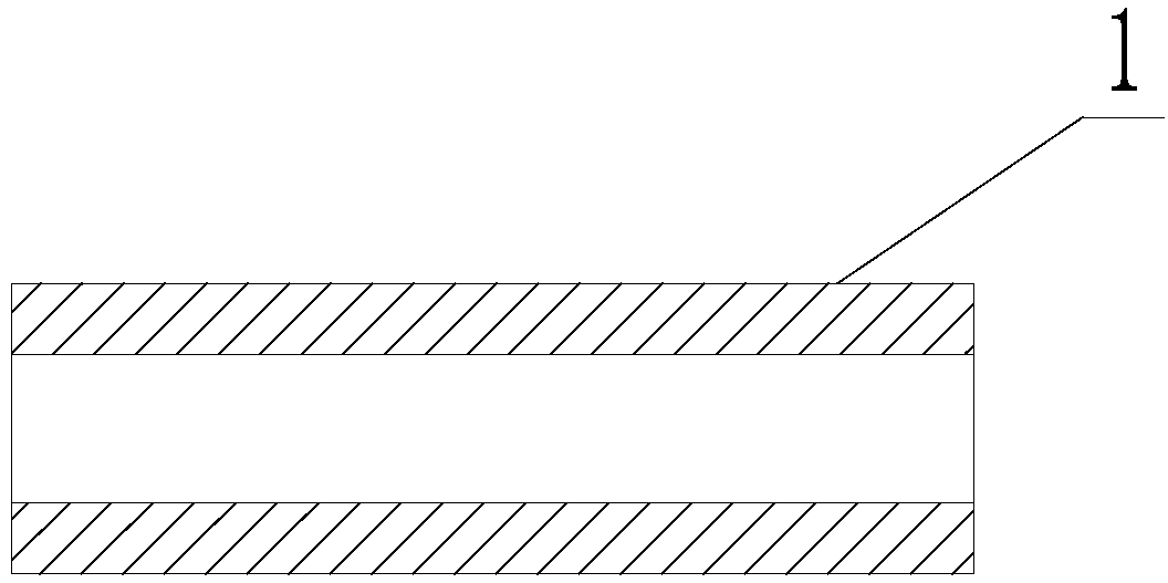
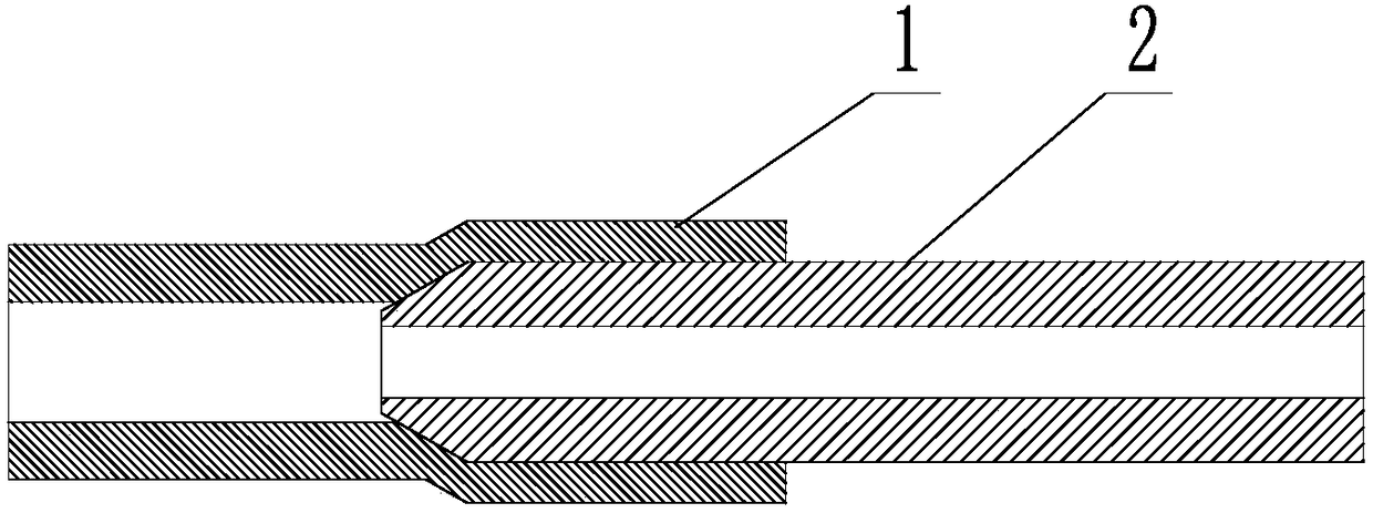
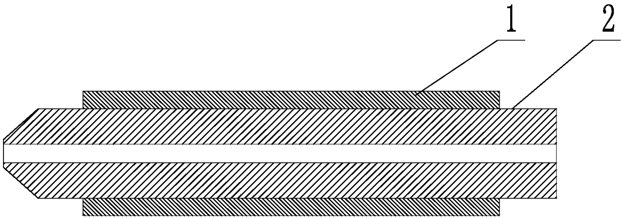
[0040] A method for processing a thin-walled sleeve, comprising a forming process step, the forming process step is: processing a blank 1 in a cylindrical shape with a circular through hole on it into a finished product size, in the forming process step, first adopt The cylindrical mandrel 2 constrains the blank 1: the mandrel 2 is inserted into the through hole, and the connection relationship between the through hole and the mandrel 2 is an interference connection; then the outer circle of the blank 1 is processed: the mandrel 2 is fixed on a On the equipment that drives the mandrel 2 to rotate around the axis of the mandrel 2 itself, the outer circle of the billet 1 is processed to the outer circle of the finished product during the process of the billet 1 rotating with the mandrel 2;

[0041] And the aperture of the through hole is processed into the aperture of the finished product through the following method: through the interference connection, the blank 1 is plasticall...

Embodiment 2

[0051] This embodiment is further limited on the basis of Embodiment 1: as a specific implementation of processing the outer circle of the blank 1, the mandrel 2 is fixed on the equipment that can drive the mandrel 2 to rotate around its own axis, and the outer circle of the blank 1 is processed. The size from the circle to the outer circle of the finished product is: fix the mandrel 2 on the chuck of the lathe, use the lathe to process the outer circle of the blank 1, and process the outer circle of the blank 1 to the size of the outer circle of the finished product. This plan is a specific plan for processing the outer circle of the blank 1 with a lathe, but as a person skilled in the art, due to the connection relationship between the blank 1 and the mandrel 2, the outer circle of the blank 1 can also be processed by other plans, such as equipment Only the blank 1 is driven to rotate synchronously with the mandrel 2, and the outer circle of the blank 1 is processed by grindi...

Embodiment 3

[0060] This embodiment is further limited on the basis of the technical solution provided in Example 1: in the process of processing the outer circle of the blank 1, along the axial direction of the blank 1, only the partial section 3 of the blank 1 is processed to the size of the outer circle of the finished product. Round size, the blank 1 has a thick-walled section 5 with a wall thickness greater than that of the local section 3 . With this scheme, when the outer circle of the blank 1 is processed after the reaming is completed, there is a greater interaction force between the thick-walled section 5 and the mandrel 2 than between the local section 3 and the mandrel 2, so that Ensure that when the outer circle of the blank 1 is processed, there will be no relative rotation between the mandrel 2 and the blank 1 or the relative rotation will not easily occur to affect the machining of the outer circle of the blank 1; at the same time, when the mandrel 2 is separated from the bl...


PUM


Abstract

The invention discloses a thin-wall sleeve machining method. The thin-wall sleeve machining method comprises a molding machining step. The molding machining step comprises the steps that a cylindricalblank of which a through hole is a circular through hole is machined to have the finished product size, and in the molding machining step, a cylindrical core rod is adopted to constrain the blank firstly, specifically, the core rod is inserted into the through hole, and the through hole is in interference connection with the core rod; then the outer circle of the blank is machined, specifically,the core rod is fixed to equipment capable of driving the core rod to rotate around the axis of the core rod, and the outer circle of the blank is machined to have the finished product outer circle size in the process that the blank rotates along with the core rod; and the through hole diameter is machined into the finished product through hole diameter through the following step that the blank generates plastic deformation under the action of the core rod through interference connection till the through hole diameter is machined into the finished product through hole diameter. The machining method is simple in process and suitable for thin-wall sleeve batch production on the condition that the thin-wall sleeve machining quality is guaranteed.

Description

technical field [0001] The invention relates to the technical field of processing cylindrical parts, in particular to a method for processing thin-walled sleeves. Background technique [0002] CRDM is the abbreviation of "Control Rod Drive Mechanism". It is the servo mechanism of the reactor control and protection system. And make it quickly inserted into the core, and then complete the functions of starting the reactor, adjusting power, maintaining power, normal shutdown and accident shutdown. [0003] At present, most of the CRDMs in marine nuclear power reactors are motor-type CRDMs. The motor-type CRDMs have the disadvantages of high failure rate and inconvenient use. : A technical solution for shielded motor type CRDM, which includes a technical feature spacer, which is actually a shielding cover. Various complex problems caused by changes, providing a strong guarantee for the reliable operation of the reactor in the water and high temperature and high humidity enviro...

Claims


Application Information

Patent Timeline
Patent Type & Authority Applications(China)
IPC IPC(8): B23P13/02
CPCB23P13/02
Inventor 王小红刘茂福黄朝辉刘深铭杜江丽
Owner SICHUAN HUADU NUCLEAR EQUIP MFR
Why Eureka
Try Eureka