Calibration circuit applied to signal chain analog gain and calibration method thereof

A technology of analog gain and calibration circuit, which is applied in the direction of analog/digital conversion calibration/test, electrical components, analog/digital conversion, etc. It can solve problems affecting chip cost, operational amplifier bandwidth and stability, etc., and achieve outstanding substantive features , avoid performance impact, and reduce the effect of area requirements

Inactive Publication Date: 2018-09-18
3PEAK INC
View PDF5 Cites 7 Cited by
  • Summary
  • Abstract
  • Description
  • Claims
  • Application Information

AI Technical Summary

Problems solved by technology

If the system has N-bit calibration, the area occupied by the switch resistor and the additional parasitic capacitance are very considerable, which also affects the chip cost and the bandwidth and stability of the op amp.

Method used


Image

  • Calibration circuit applied to signal chain analog gain and calibration method thereof
  • Calibration circuit applied to signal chain analog gain and calibration method thereof

Examples


Embodiment Construction

[0017] The specific implementation of the present invention will be described in further detail below in conjunction with the accompanying drawings of the embodiments, so as to make the technical solution of the present invention easier to understand and grasp, so as to define the protection scope of the present invention more clearly.

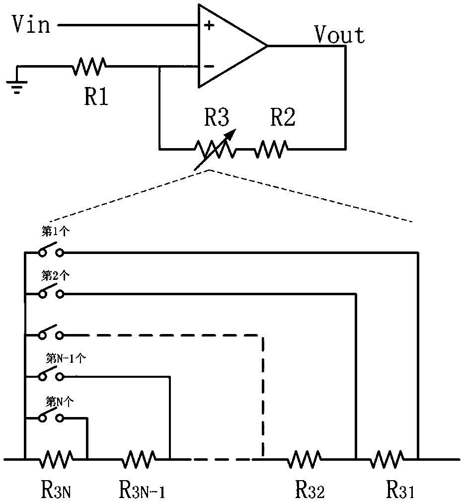
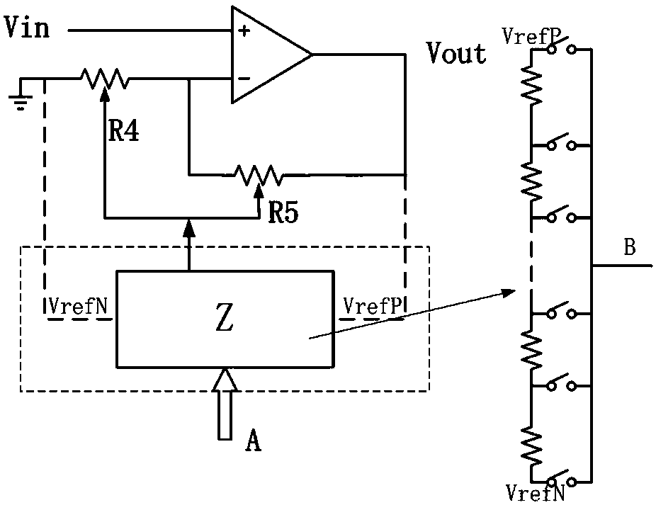
[0018] Aiming at the deficiencies in the calibration of the analog gain of the existing signal chain, the designers of the present invention have integrated years of experience in this industry, and are committed to proposing a breakthrough in the technical improvement of the calibration resistor link of the analog gain.

[0019] In order to facilitate the understanding of the practicability and advantages of the innovative solution of the present invention, a brief introduction of the Poly resistor on which the technical solution of the present invention is implemented is firstly introduced. Poly resistors are a unique type of resistors in CMO...


PUM


Abstract

The invention discloses a calibration method for a calibration circuit applied to a signal chain analog gain. The calibration circuit is disposed on the auxiliary path of an amplifier in a signal transmission device and is composed of a first Poly resistor, a second Poly resistor and a calibration voltage generator of a reference voltage Vref; the calibration voltage generator is a digital analogconverter consisting of a string of common resistors and a switch array, and the output of the calibration voltage generator is connected to the substrates of the two Poly resistors for voltage regulation. By applying the calibration circuit and calibration method thereof provided by the invention, the calibration circuit is capable of realizing the calibration of ultra-high precision analog gainby using the voltage coefficient characteristic of the Poly resistor, and the calibration process is not in the signal main path, thereby avoiding the performance impact on the PGA main path, greatlyreducing the area requirement of the calibration circuit, and avoiding the overhead and cost of the unit resistance for calibrating and the chip area occupied by the calibration switch. In addition, the calibration circuit is capable of avoiding the influence of introducing the dynamic performance of the PGA and increasing the voltage linearity of the PGA.

Description

technical field [0001] The invention relates to the field of analog gain calibration of a signal transmission device, in particular to an ultra-high-precision analog gain calibration circuit and a calibration method thereof. Background technique [0002] With the rapid development of communication technology, the hardware chip design, which is related to the hardware foundation, is also undergoing revolutionary fusion-type development. In the signal transmission device, in order to improve the analog gain of the signal chain transmission, it is necessary to realize the resistance matching. Traditional calibration circuits are implemented using calibration resistors, specifically, as figure 1 As shown, the calibration resistor needs to be generated by parallel connection of unit resistors, so the area of ​​the resistor and the parasitic capacitance are relatively large. In the scheme shown in the figure, the gain of the PGA is 1 and the gain accuracy needs to be controlled ...

Claims


Application Information

Patent Timeline
Patent Type & Authority Applications(China)
IPC IPC(8): H03M1/10
CPCH03M1/1014
Inventor 吴建刚
Owner 3PEAK INC
Why Eureka
Try Eureka