Eureka AIR delivers breakthrough ideas for toughest innovation challenges, trusted by R&D personnel around the world.

Gas treatment device for electric control room under coal mine

An electrical control room and gas treatment technology, applied in the directions of dispersed particle separation, chemical instruments and methods, separation methods, etc., can solve problems such as poor working conditions, safety accidents, and narrow underground tunnel space, and achieve the effect of convenient and flexible installation and debugging.

Inactive Publication Date: 2018-09-21
XUCHANG YONGXIN ELECTRIC
View PDF0 Cites 5 Cited by
  • Summary
  • Abstract
  • Description
  • Claims
  • Application Information

AI Technical Summary

Problems solved by technology

Grasping the establishment of a system of safety management measures for coal mine electrical equipment is of great significance to the safe operation of coal mines, which can minimize or even avoid the occurrence of major safety accidents in coal mines. In the production process of coal mines, there are many mechanical equipment and working ground conditions Complex, the underground roadway space is narrow, the air is humid, the working conditions are harsh, there are various uncertain factors in the working environment, electrical equipment and cables are easily crushed and the insulation is damaged, and various safety accidents are prone to occur underground

Method used


Image

  • Gas treatment device for electric control room under coal mine
  • Gas treatment device for electric control room under coal mine
  • Gas treatment device for electric control room under coal mine

Examples


Embodiment 1

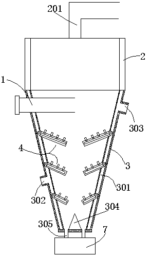
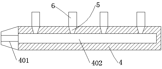
[0038] In this embodiment, the structure of the conical cylinder and the ventilation partition is as follows: it includes a hollow shell and a draft tube 1 for guiding the air flow, and the shell includes a cylindrical part 2 with a cylindrical upper end and a cylindrical part with a lower end. The conical conical part 3 is provided with a gas discharge port 201 on the cylindrical part 2, and a hollow interlayer is provided in the housing wall of the conical part 3. The outer wall is provided with a cold air inlet 302 and a cold air outlet 303 connected to the cold air passage 301. The cold air inlet 302 is connected to the existing cold source in the electrical control room through the connecting pipeline, and the cold air outlet 303 is connected to the circulation pipeline. Connected to realize air circulation, on the inner wall of the conical part 3, there are several downward-sloping ventilation partitions 4, and several of the ventilation partitions 4 are spaced up and dow...

Embodiment 2

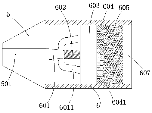
[0040] The structure of the conical cylinder and the ventilation partition in this embodiment is the same as that in Embodiment 1, the main difference is that the structure of the gas nozzle is different, so only the structure of the gas nozzle is described here, such as Figure 4 As shown, the gas nozzle structure includes a screw joint 5 and a pipe body 6 connected to the screw joint. Evening plate 604, buffer chamber 605, dispersing plate 606 and exhaust port 607, the airflow channel II501 in the screw joint and the air inlet chamber 601 realize sealing butt joint, and several cone-shaped The vent hole 6041, the larger end of the vent hole 6041 faces the air storage chamber 603, a cotton layer is arranged in the buffer chamber 605, and a plurality of through holes are arranged on the dispersion plate 606, and the through holes are located in the dispersion It is composed of a central hole in the middle of the plate and a plurality of inclined divergent holes arranged around...


PUM

PropertyMeasurementUnit
angleaaaaaaaaaa

Abstract

The invention relates to a gas treatment device for an electric control room under a coal mine. The gas treatment device comprises a hollow shell and an airflow guide pipe used for guiding the airflow, wherein the shell comprises a cylindrical part and a circular cone part, wherein the upper end of the cylindrical part is in a cylindrical shape, and the lower end of the circular cone part is in acircular cone shape; the shell wall of the circular cone part is internally provided with a cold airflow channel; the inner wall of the circular cone part is provided with a plurality of aeration spacer plates which incline downwards; the plurality of aeration spacer plates are arranged up and down at intervals and are arranged on the inner wall of the circular cone part at the equal intervals; each aeration spacer plate is internally provided with an airflow channel I, and the airflow channels I are communicated with the cold airflow channel of the circular cone part; the aeration spacer plates are separately provided with an air nozzle structure used for discharging cold air; a material dispersing cone is arranged at the middle lower part of an inner cavity of the circular cone part, andthe bottom end of the circular cone part is provided with a plurality of outlet pipes. The gas treatment device can be arranged at a gas inlet of the electric control room in a matching way, so thatthe external oily and dusty gases can be effectively treated by purifying, the air quality in the electric control room is improved, the safety of electrical equipment of the coal mine is improved, and the service life of the electrical equipment of the coal mine is prolonged.

Description

technical field [0001] The invention relates to a gas treatment device for purifying external gas containing oil and dust, in particular to a gas treatment device for an electrical control room under a coal mine. Background technique [0002] At present, as the country pays more and more attention to safety issues in coal mining, some small coal mines with high pollution and poor equipment are gradually shutting down or suspending business for a long time for rectification, and large coal mining groups are also becoming more and more Pay attention to the safety management of coal mine electrical equipment, which is related to the survival of countless workers' families. [0003] The coal mine electrical equipment in the electrical control room under the coal mine is the core of the management of the entire coal mine. The safe and reliable operation of the underground electrical equipment is not only related to the safe production of the mine, but also related to the life saf...

Claims


Application Information

Patent Timeline
Patent Type & Authority Applications(China)
IPC IPC(8): B01D45/08B01D45/16B01D53/00
CPCB01D45/08B01D45/16B01D53/002
Inventor 彭付强于金要郭锋
Owner XUCHANG YONGXIN ELECTRIC
Why Eureka
Eureka Blog
Learn More