Laser cutting device of high borosilicate glass tube

A high borosilicate glass and laser cutting technology, which is applied in laser welding equipment, welding equipment, metal processing equipment, etc., can solve the problems of high borosilicate glass tubes being fragile, safety performance defects, and rough incisions, etc., and achieve simple structure , avoid direct exposure, and reduce the effect of defective rate

Inactive Publication Date: 2018-09-21
明光市丰亿科技有限公司
View PDF0 Cites 6 Cited by
  • Summary
  • Abstract
  • Description
  • Claims
  • Application Information

AI Technical Summary

Problems solved by technology

[0002] High borosilicate glass tubes are widely used in the solar energy industry because of their excellent physical properties. With the development of society, traditional diamond cutting machines have been gradually replaced by laser cutting devices. Laser cutting devices are lasers emitted from lasers. The optical path system is focused into a laser beam with high power density. The laser beam is irradiated on the surface of the workpiece to make the workpiece reach the melting point or boiling point. As the beam and the workpiece move along the horizontal axis, the vertical axis and the vertical axis, the material finally forms a slit. In order to achieve the purpose of cutting; the existing laser cutting device has certain disadvantages in use. In the process of cutting, technicians often encounter problems such as rough incision or impenetrable cut. This is because the optical path of the laser is not correct. However, it cannot meet the needs of many aspects of use, which has brought certain limitations to people's use. The traditional laser cutting machine tool is directly exposed. Although the operator wears protective clothing, due to the extremely fast laser cutting speed, it may cause Some leftovers fly out and cause injuries, and there are certain defects in safety performance. The high borosilicate glass tube is fragile. If the high borosilicate glass tube is not fixed, it will cause displacement and collide with each other and break. brought a certain impact, for this reason, we propose a laser cutting device for high borosilicate glass tubes

Method used


Image

  • Laser cutting device of high borosilicate glass tube
  • Laser cutting device of high borosilicate glass tube
  • Laser cutting device of high borosilicate glass tube

Examples


Embodiment Construction

[0017] In order to make the technical means, creative features, goals and effects achieved by the present invention easy to understand, the present invention will be further described below in conjunction with specific embodiments.

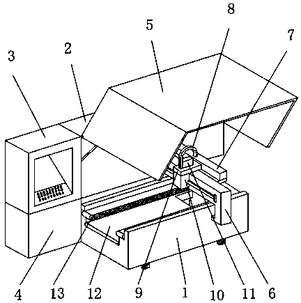
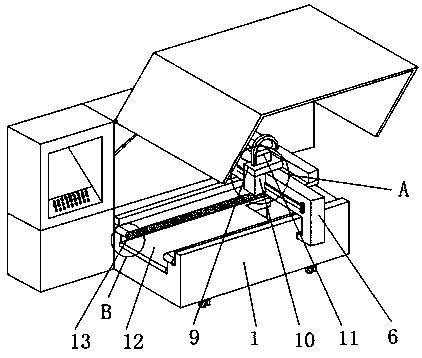
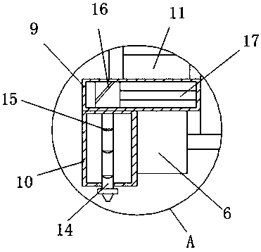
[0018] Such as Figure 1-4 As shown, a laser cutting device for high borosilicate glass tubes includes a workbench main body 1 and a mounting beam 6. An equipment box 2 is fixedly installed on one end of the outer surface of the workbench main body 1, and the outer surface of the equipment box 2 is connected to the One end adjacent to the workbench main body 1 is provided with a control box 3, the lower end of the outer surface of the control box 3 is fixedly installed with an electric box 4, and the end of the outer surface of the equipment box 2 close to the workbench main body 1 is provided with a movable protective cover 5, and the installation beam 6 is fixedly installed above the outer surface of the workbench main body 1, a laser generator ...


PUM


Abstract

The invention discloses a laser cutting device of a high borosilicate glass tube. The laser cutting device comprises a worktable body and a mounting beam; an equipment box is fixedly arranged at one end of the outer surface of the worktable body, a control box is arranged at the end, adjacent to the worktable body, of the outer surface of the equipment box, an electric box is fixedly arranged at the lower end of the outer surface of the control box, a movable protection cover is arranged at the end, close to the worktable body, of the outer surface of the equipment box, and the mounting beam is fixedly arranged above the outer surface of the worktable body. The laser cutting device of the high borosilicate glass tube is provided with the movable protection cover, a focusing lens, a side pressing wheel and a fabric belt, leftover materials of the laser cut glass tube can be prevented from injuring a person, the laser cutting time can be shortened, collision damage happening in the conveying process of the high borosilicate glass tube can be avoided, the device is suitable for different work conditions, and the better use prospects are achieved.

Description

technical field [0001] The invention relates to the field of laser cutting devices, in particular to a laser cutting device for high borosilicate glass tubes. Background technique [0002] High borosilicate glass tubes are widely used in the solar energy industry because of their excellent physical properties. With the development of society, traditional diamond cutting machines have been gradually replaced by laser cutting devices. Laser cutting devices are lasers emitted from lasers. The optical path system is focused into a laser beam with high power density. The laser beam is irradiated on the surface of the workpiece to make the workpiece reach the melting point or boiling point. As the beam and the workpiece move along the horizontal axis, the vertical axis and the vertical axis, the material finally forms a slit. In order to achieve the purpose of cutting; the existing laser cutting device has certain disadvantages in use. In the process of cutting, technicians often ...

Claims


Application Information

Patent Timeline
Patent Type & Authority Applications(China)
IPC IPC(8): B23K26/38B23K26/402
CPCB23K26/38B23K26/402
Inventor 王滨
Owner 明光市丰亿科技有限公司
Why Eureka
Try Eureka