Edge Error Control Method in Optical Processing of Small Grinding Head for Optical Lens

An optical lens and optical processing technology, which is applied in the field of optical parts processing, can solve the problems of increasing the cost of processing equipment and application range, difficulty in controlling the processing quality of edge parts, and warping, so as to reduce polishing costs, reduce convergence difficulty, and improve processing. efficiency effect

Active Publication Date: 2020-01-10
FUDAN UNIV
View PDF5 Cites 0 Cited by
  • Summary
  • Abstract
  • Description
  • Claims
  • Application Information

AI Technical Summary

Problems solved by technology

When the small grinding head is at the edge of the workpiece, due to the change of the pressure at each point in the contact area, there will be a nonlinear removal in the actual processing, which makes the processing quality of the edge part extremely difficult to control, and it is very easy to produce the so-called "sag edge". " and "warping" phenomenon
The solution to this kind of edge error is to find processing tools that are not affected by the edge position, but this will inevitably greatly increase the cost and application range of processing equipment

Method used


Image

  • Edge Error Control Method in Optical Processing of Small Grinding Head for Optical Lens
  • Edge Error Control Method in Optical Processing of Small Grinding Head for Optical Lens
  • Edge Error Control Method in Optical Processing of Small Grinding Head for Optical Lens

Examples


Embodiment

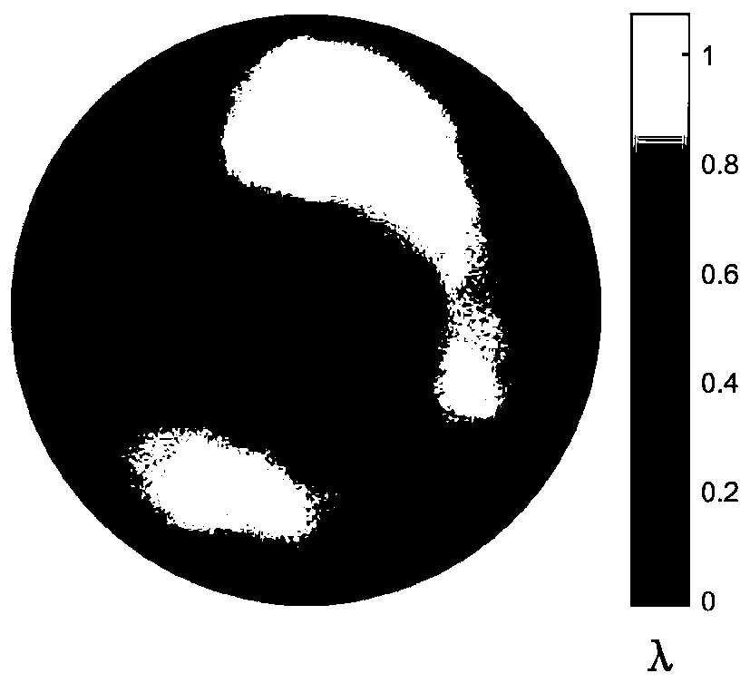
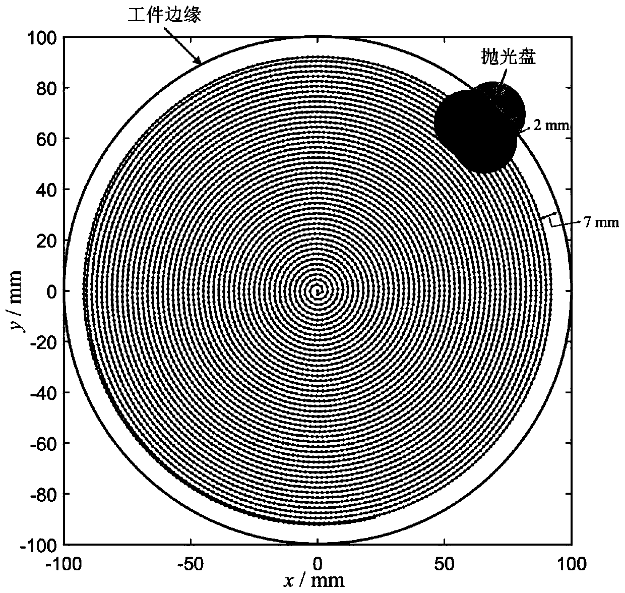
[0037] The polishing process of this embodiment is carried out on a polishing equipment based on industrial robots. The process parameters are set as follows: small grinding head diameter 25mm, applied pressure 10N, revolution speed 119rpm, rotation speed 200rpm, and the composition of the polishing liquid is CeO 2 , The concentration is 10% w.t, the ambient temperature is 23°C, the test workpiece to be polished is a concave BK7 optical glass with a diameter of 200mm, the radius of curvature is 1500mm, and the path is chosen as the Archimedes spiral.

[0038] Polish the workpiece by the following methods:

[0039] 1. Detecting surface error distribution: using laser interferometer to detect surface error of the workpiece to be polished, the results are as follows figure 1 Shown

[0040] 2. Face shape adjustment: Use face shape adjustment technology to fine-tune the measured face shape. The parameter α in formula (1) is 0.7 and β is 2×10. -7 mm. Get adjusted back shape like figure 2...


PUM


Abstract

The invention belongs to the technical field of optical element machining, and particularly discloses an edge error control method in optical lens small grinding head optical machining. The edge errorcontrol method comprises specific steps that firstly, a workpiece is measured to obtain a surface shape error, an appropriate quadratic term is added to the surface removing amount for adjustment, and the edge machining difficulty is lowered; meanwhile, a polishing path is abstracted to discrete sampling points, and a removing function of each sampling point is calculated according to a removingfunction model; then, the residence time is solved through a space variation deconvolution algorithm; and finally, a control program is generated according to the polishing path and the residence time, and polishing is carried out on the workpiece. The removing function changing along with the position is adopted to solve the residence time, and the removing amount of the edge part can be precisely controlled; the non-linear deconvolution algorithm can adapt to the shifting removing function; and by means of the surface shape adjusting technology, the convergence difficulty of the edge error is lowered to the maximum extent. According to the edge error control method, the requirement for the control precision of a polishing system is relatively low, and therefore the small grinding head polishing cost can be reduced, and the machining efficiency is improved.

Description

Technical field [0001] The invention belongs to the technical field of optical parts processing, and specifically relates to an edge error control method in optical lens processing. Background technique [0002] In modern optical processing, computer controlled surface shaping (CCOS) is usually used to process various optical components. The basic principle of CCOS is to use a grinding head much smaller than the diameter of the workpiece according to the surface error data to realize the quantitative removal of the material at each point of the surface through the computer control of its residence time at each point on the workpiece. When the small grinding head is at the edge of the workpiece, the actual processing will have a non-linear removal due to the change of the pressure at each point in the contact area, which makes the processing quality of the edge part extremely difficult to control, and it is very easy to produce the commonly known "sag ”And “edge warping” phenomen...

Claims


Application Information

Patent Timeline
Patent Type & Authority Patents(China)
IPC IPC(8): B24B13/00B24B51/00
CPCB24B13/00B24B51/00
Inventor 万嵩林张祥朝徐敏
Owner FUDAN UNIV
Why Eureka
Try Eureka