Thin-wall sliding sleeve disassembling fixture

A technology for dismantling tooling and sliding sleeves, applied in manufacturing tools, hand-held tools, etc., can solve the problem of difficult disassembly of thin-walled sliding sleeves, and achieve the effects of avoiding deformation and scratching of the hole wall, smooth movement, and safe and convenient operation.

Pending Publication Date: 2018-09-21
YANTAI JEREH PETROLEUM EQUIP & TECH CO LTD
View PDF6 Cites 115 Cited by
  • Summary
  • Abstract
  • Description
  • Claims
  • Application Information

AI Technical Summary

Problems solved by technology

[0003] The purpose of the present invention is to overcome the problem of difficult disassembly of thin-walled sliding sleeves, and provide a thin-walled sliding sleeve removal tool, which can ensure that the hole wall is not scratched and can effectively remove the sliding sleeve.

Method used


Image

  • Thin-wall sliding sleeve disassembling fixture
  • Thin-wall sliding sleeve disassembling fixture
  • Thin-wall sliding sleeve disassembling fixture

Examples


Embodiment Construction

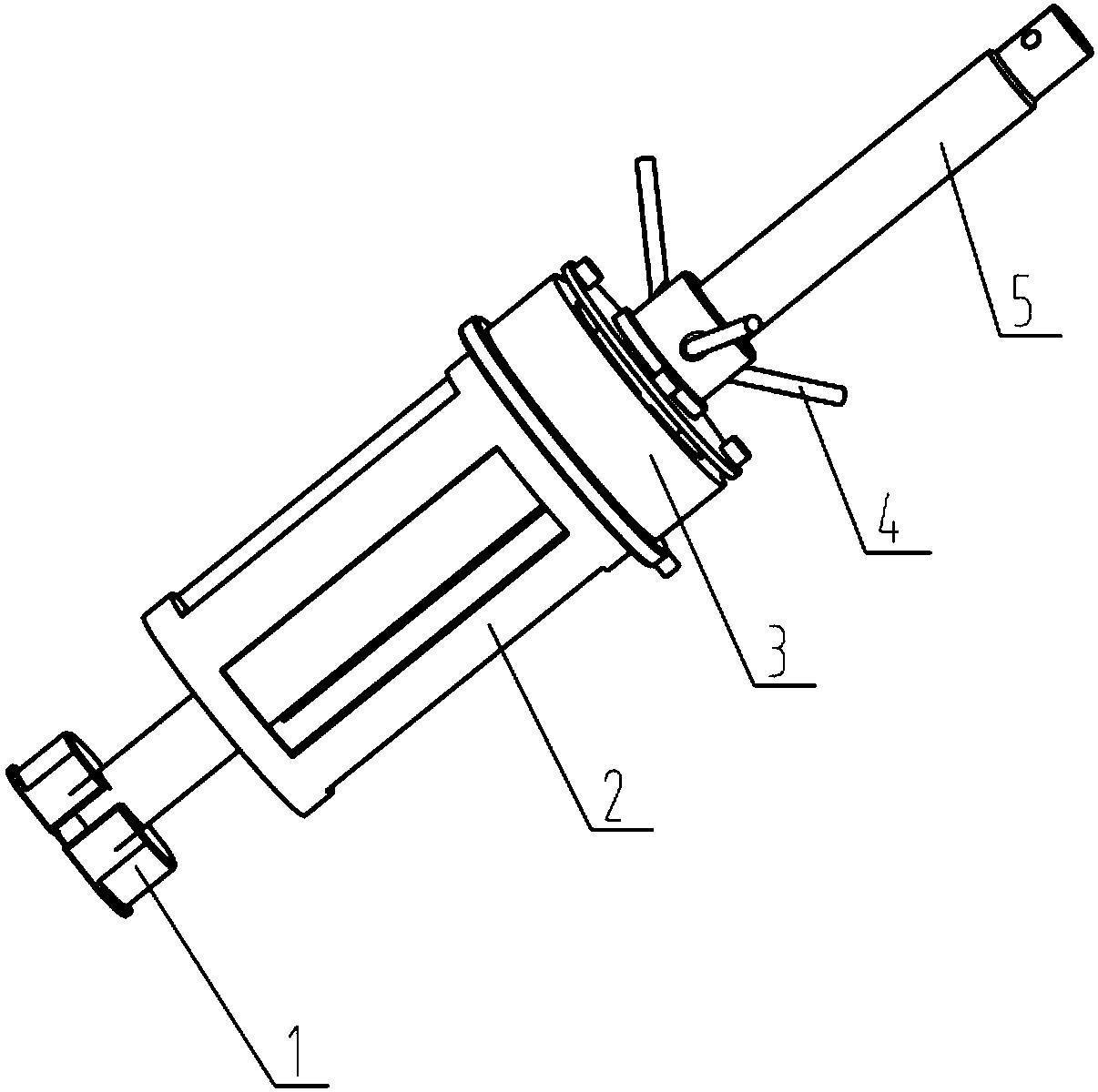
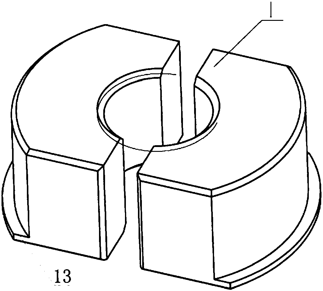
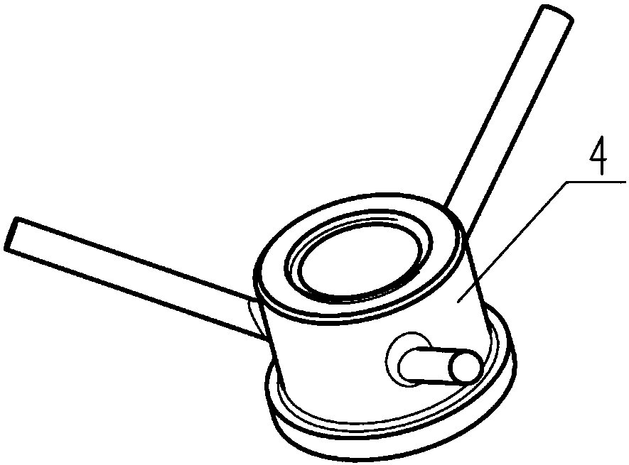
[0024] Examples such as Figures 1 to 7 As shown, a thin-walled sliding sleeve disassembly tooling includes a puller nut 4 and a puller screw 5, the puller screw 5 is threaded with the puller nut 4, and one end of the puller screw 5 is provided with Claw 1, puller screw 5 is threadedly connected with claw 1, bracket 2 and hydraulic system 3 are arranged between puller nut 4 and claw 1, bracket 2 and hydraulic system 3 are set on the puller screw 5, the bracket 2 is close to the claw 1, the hydraulic system 3 is close to the puller nut 4, the claw 1 is a two-body type, and the outer circumference of the bottom of the claw 1 is provided with a step 13, and the surface of the step can contact the end surface of the thin-walled sliding sleeve 6, The inner peripheral surface of the claw 1 away from the end of the step 13 is provided with an internal thread, the hydraulic system 3 includes a hydraulic base 8, the hydraulic base 8 is set with a hydraulic cylinder 11, the outer circum...


PUM


Abstract

The invention provides a thin-wall sliding sleeve disassembling fixture. The thin-wall sliding sleeve disassembling fixture comprises a puller nut and a puller screw. The puller screw is in threaded connection with the puller nut. One end of the puller screw is provided with a clamping jaw. The puller screw is in threaded connection with the clamping jaw. A bracket and a hydraulic system are installed between the puller nut and the clamping jaw. The bracket and the hydraulic system are sheathed on the puller screw. The bracket is adjacent to the clamping jaw. The hydraulic system is adjacent to the puller nut. Through controlling the hydraulic system to boost pressure and reduce pressure, the disassembly of a thin-wall sliding sleeve can be realized. The thin-wall sliding sleeve disassembling fixture is small in volume, light in weight, smooth and steady in movement, and safe and convenient in operation, and capable of preventing the deformation of the thin-wall sliding sleeve and thescratching of a hole wall in an disassembling process.

Description

technical field [0001] The invention relates to the field of hand tools for oilfield equipment, in particular to a thin-wall sliding sleeve removal tool. Background technique [0002] In oil field equipment, some thin-walled sliding sleeves or copper sleeves are often installed on the power end structure of some plunger pumps and other products to support the reciprocating linear motion of the piston or crosshead in it. For example, a cross-head sliding sleeve of a plunger pump, because the sliding sleeve is relatively thin, the wall thickness of one side is only 4-5mm, and the hole installed with it is an interference fit, which can be compressed by cold fitting and hydraulic tools during assembly. , the ordinary puller cannot be effectively disassembled during replacement, and the strong disassembly is likely to cause strain on the hole wall, which brings great difficulties to the disassembly of the thin-walled sliding sleeve. There is an urgent need for a type that can en...

Claims


Application Information

Patent Timeline
Patent Type & Authority Applications(China)
IPC IPC(8): B25B27/06
CPCB25B27/062
Inventor 李朋
Owner YANTAI JEREH PETROLEUM EQUIP & TECH CO LTD
Why Eureka
Try Eureka