
Seat electric rotation mechanism

A technology of electric rotation and seats, which is applied in the direction of movable seats, vehicle seats, special positions of vehicles, etc., can solve the problems of heavy weight, large space occupation, complex structure, etc., and achieves few parts, small space occupation, The effect of simple structure

Active Publication Date: 2020-09-25
YANFENG ADIENT SEATING CO LTD
View PDF4 Cites 2 Cited by
  • Summary
  • Abstract
  • Description
  • Claims
  • Application Information

AI Technical Summary

Problems solved by technology

There are following problems in these technical schemes: 1. complex structure, many parts quantity; 2.
Multi-stage transmission takes up a lot of space; 3. Non-modularization makes it inconvenient to apply different seat frames; 4. Parts are machined and heavy, which is not conducive to mass production
5. Low peel strength

Method used


Image

  • Seat electric rotation mechanism
  • Seat electric rotation mechanism
  • Seat electric rotation mechanism

Examples


Embodiment Construction

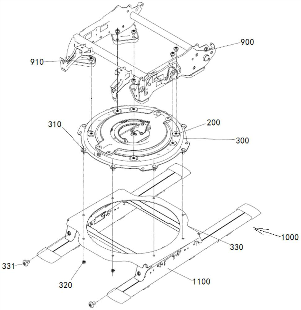
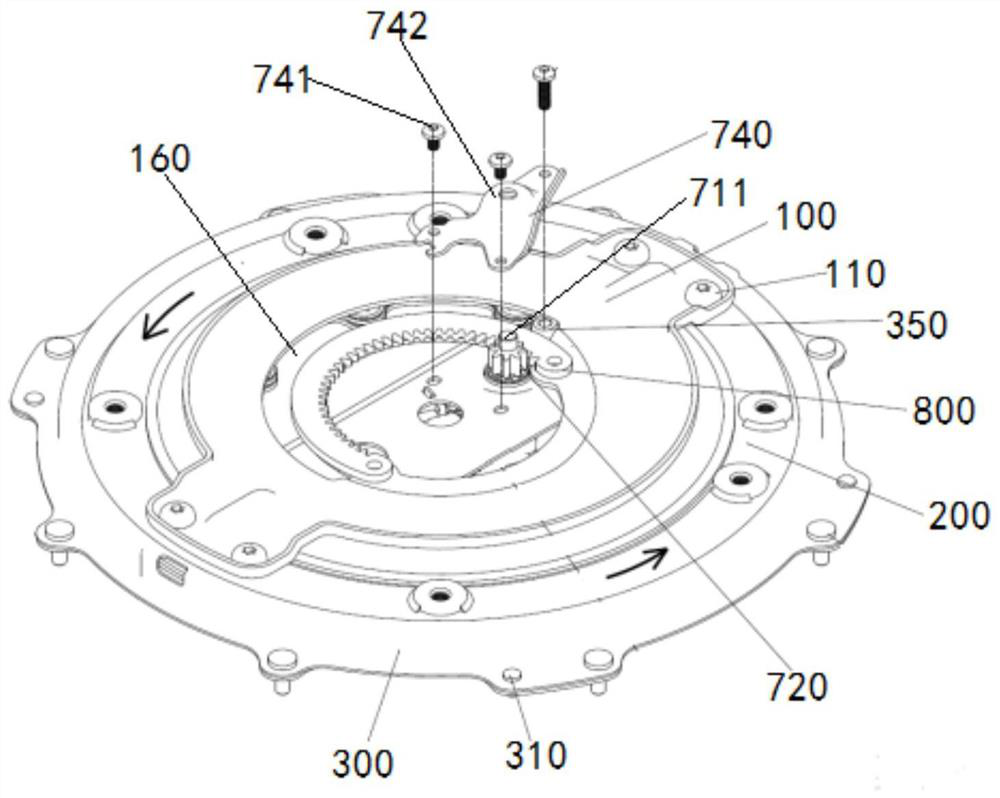
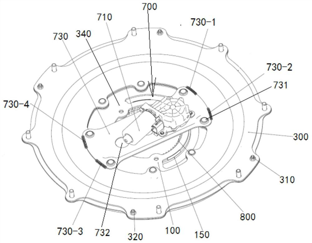
[0050] see Figure 4 and Figure 5, the seat electric rotating mechanism shown in the figure includes a rotating bracket 100, a rotating disk 200, a fixed disk 300, a pressure plate 400, an upper ball assembly 500, a lower ball assembly 600, a drive motor assembly 700 and a semicircular rack 800 . The above-mentioned rotating bracket 100, rotating disc 200, fixed disc 300, pressure plate 400, semicircular rack 800, upper ball cage 520 in the upper ball assembly 500, and lower ball cage 620 in the lower ball assembly 600 are all stamped. It has the advantages of high strength and light weight.

[0051] see in conjunction figure 1 , there are 6 M10 nuts 200-1, 200-2, 200-3, 200-4, 200-5, 200-6 spot welded on the rotating disk 200, and the seat cushion frame 900 in the seat is screwed in by 6 Bolts 910 of six M10 nuts 200-1, 200-2, 200-3, 200-4, 200-5, 200-6 are fixedly connected with the rotating disk 200 .

[0052] Eight M8 bolts 310 are spot-welded on the fixed plate 300,...


PUM


Abstract

The seat electric rotating mechanism disclosed in the present invention includes: a rotating bracket, a rotating disk, a fixed disk, a pressure plate, an upper ball assembly, and a lower ball assembly; it also includes: a driving motor assembly, which is installed on the fixed disk, The driving motor assembly includes a driving gear; a semicircular rack mounted on the rotating bracket, the center of the semicircular rack coincides with the center of rotation of the rotating bracket, and the semicircular rack meshes with the driving gear; in the driving motor assembly The driving gear drives the rotating bracket to rotate back and forth between 0° and 180° through a semicircular rack. The seat electric rotating mechanism of the present invention only needs a single-stage transmission of the driving motor assembly, the driving gear, and the semicircular rack to realize the reciprocating rotation of the seat between 0° and 180°, and has the advantage that the space occupied by the transmission mechanism is small . At the same time, avoid the unrestricted rotation of the seat wire harness and twist it off.

Description

technical field [0001] The invention relates to the technical field of car seats, in particular to an electric rotating mechanism for a seat. Background technique [0002] At present, the rotating mechanism used to rotate the car seat around the vertical axis is divided into two types: rolling rotating mechanism and sliding rotating mechanism according to the different rotating medium. The rolling rotary mechanism uses a plurality of hard balls preset in the cage as the rotating medium to make the rotor rotate in the circular track formed by the upper and lower rows of balls. At present, the rolling rotating mechanism has some technical solutions disclosed in Chinese patents CN103661017B, CN205292658U, CN205632178U, and CN206067762U. These technical solutions have the following problems: 1. The structure is complex and the number of parts is large; 2. Multi-stage transmission takes up a lot of space; 3. Non-modularization makes it inconvenient to apply different seat frame...

Claims


Application Information

Patent Timeline
Patent Type & Authority Patents(China)
IPC IPC(8): B60N2/14B60N2/02
CPCB60N2/14B60N2/02246
Inventor 封庆伟丁佳彬朱斐翔
Owner YANFENG ADIENT SEATING CO LTD
Learn More