Clothes dewatering machine applicable to industrial production

A technology of clothes dehydration and dehydration machine, which is applied in the field of clothes dehydration, which can solve the problems of low efficiency, time-consuming, damage to the rotating shaft, etc., and achieve the effects of prolonging the service life, ensuring uniformity, and compact extrusion

Pending Publication Date: 2018-09-21
广州市信宏洗衣机械有限公司
View PDF10 Cites 4 Cited by
  • Summary
  • Abstract
  • Description
  • Claims
  • Application Information

AI Technical Summary

Problems solved by technology

[0003] In the existing dehydration machine, the dehydration bucket has only one partition and has an array of small hole structure. When the external motor drives the dehydration bucket to rotate, the clothes inside are easy to collide with each other and entangled. A large number of clothes are entangled together, making it difficult to Separation, many workers use too much force during the separation process, which often leads to damage to the clothes
In addition, the clothes need to be evenly distributed in the dehydration bucket, otherwise, under high-speed rotation, the entangled clothes will form a heavy rotating eccentric core, which will hit the wall of the dehydration bucket, which will cause great damage to the rotating shaft and easily cause damage to the bucket wall
Since the industrial dehydrator is used to dehydrate a lot of clothes, generally hundreds of kilograms of water-carrying clothes, it takes a lot of time for each dehydrator to load and take out the clothes, resulting in very low efficiency.
Above-mentioned various existing technical drawbacks have all limited the popularization and application of existing industrial dehydrators.

Method used


Image

  • Clothes dewatering machine applicable to industrial production
  • Clothes dewatering machine applicable to industrial production
  • Clothes dewatering machine applicable to industrial production

Examples


Embodiment

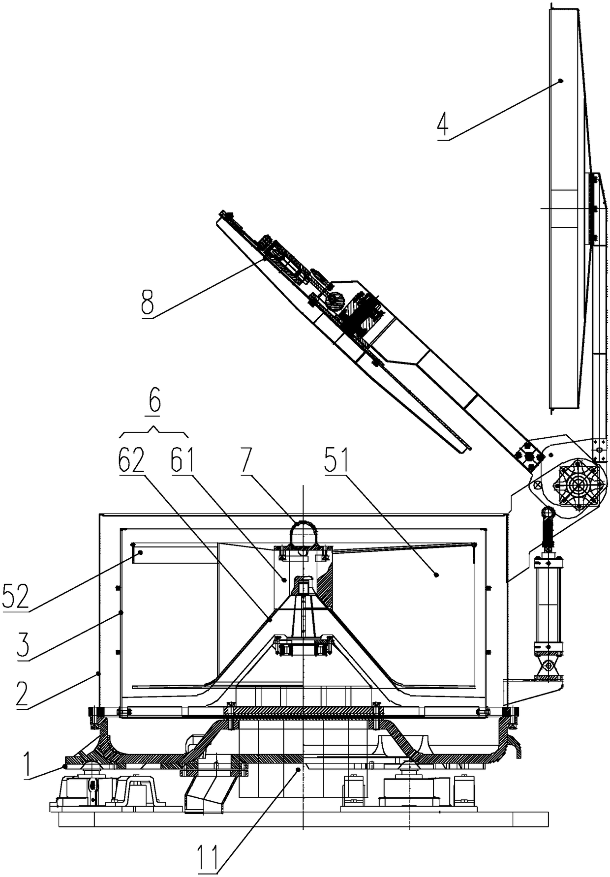
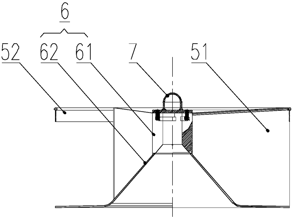
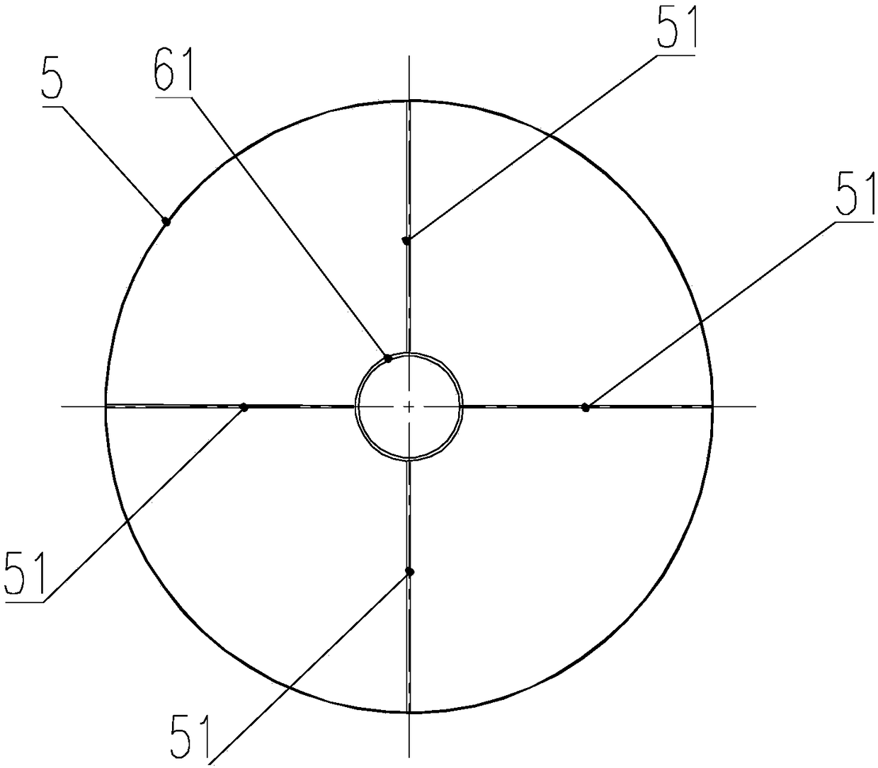
[0035] Such as figure 1 As shown, a clothes dehydrator suitable for industrial production includes a base 1, an outer barrel 2, a dehydration barrel 3, and an upper cover 4; the base 1 is provided with a rotating shaft 11 driven by a motor, and the outer barrel 2 is arranged on the base 1. Above, a number of small holes for drainage are evenly distributed on the barrel wall of the dehydration barrel 3. The dehydration barrel 3 is located in the outer barrel 2 and is driven by the rotating shaft 11 to make a circular motion. The outer barrel 2 and the top of the dehydration barrel 3 All are provided with a clothing input port, and the upper cover 4 is pressed against the outer barrel 2 by a hydraulic device; the dehydration machine is provided with a transfer barrel 5; the transfer barrel 5 is provided with a sleeve 6 and the upper part 61 of the sleeve is Cylindrical shape, the lower part 62 of the sleeve barrel is in the shape of a truncated cone; the top of the sleeve barrel 6...


PUM


Abstract

The invention relates to the field of clothes dewatering, in particular to a clothes dewatering machine applicable to industrial production. The clothes dewatering machine comprises a base, an outer drum, a dewatering drum and an upper cover. A rotating shaft driven by a motor is arranged on the base, the outer drum is arranged on the base, a plurality of small water drainage holes are uniformly distributed in the wall of the dewatering drum, and the dewatering drum is positioned in the outer drum and driven by the rotating shaft to realize circular motion. The top of the outer drum and the top of the dewatering drum are provided with clothes feeding ports respectively, and the upper cover and the outer drum are tightly pressed. A transfer drum with the top open is arranged in the dewatering machine and provided with a bottom plate and a side wall hollowed-out structure, and the internal space of the transfer drum is partitioned into a plurality of clothes storage spaces. According tothe technical scheme, the transfer drum is partitioned into a plurality of spaces internally, the space for motion of clothes under the centrifugal action is reduced, probability of twining of the clothes in rotation is sharply lowered, and impact on the dewatering drum is scattered, so that the service life of the dewatering machine is prolonged.

Description

Technical field [0001] The invention relates to the field of clothes dehydration, in particular to a clothes dehydrator suitable for industrial production. Background technique [0002] In the production process of clothing, the steps of dyeing, dehydrating, and fixing are required. Dyeing is the process of dyeing fiber materials with colors. After the clothes are dyed, they need to be washed with water to remove the floating color, and then dehydrated. After the clothes are dried, the color is fixed. In industrial production, the commonly used dewatering method is a centrifugal dewatering machine. The outer barrel is fixed and the dewatering barrel rotates, so that the clothes in the dewatering barrel complete the dehydration process under the action of centrifugal force. [0003] In the existing dehydration machine, the dehydration barrel has only one partition and has an array of small holes. When the external motor drives the dehydration barrel to rotate, the inner clothes are...

Claims


Application Information

Patent Timeline
Patent Type & Authority Applications(China)
IPC IPC(8): D06F49/00D06F49/02
CPCD06F49/00D06F49/02
Inventor 肖泽斌
Owner 广州市信宏洗衣机械有限公司
Why Eureka
Try Eureka