Method for measuring dielectric constant of large loss material

A dielectric constant and digital measurement technology, applied in the direction of measuring electrical variables, measuring resistance/reactance/impedance, measuring devices, etc., to achieve the effect of ensuring consistency, eliminating measurement errors, and fast and accurate measurement

Inactive Publication Date: 2018-09-21
NORTHEAST INST OF GEOGRAPHY & AGRIECOLOGY C A S
View PDF9 Cites 0 Cited by
  • Summary
  • Abstract
  • Description
  • Claims
  • Application Information

AI Technical Summary

Problems solved by technology

[0004] The purpose of the present invention is to solve the problem that the cylindrical resonant cavity perturbation method can only measure low dielectric constant and low loss materials, thereby providing a method for measuring the dielectric constant of large loss materials

Method used


Image

  • Method for measuring dielectric constant of large loss material
  • Method for measuring dielectric constant of large loss material
  • Method for measuring dielectric constant of large loss material

Examples


specific Embodiment approach 1

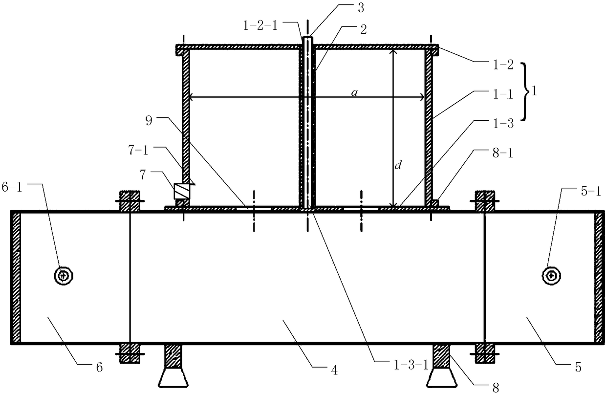
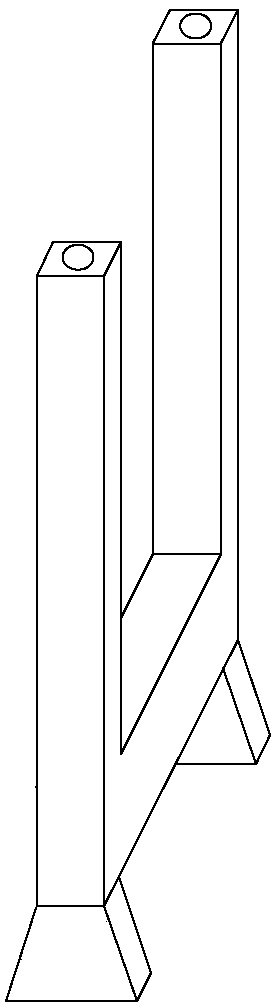
[0039] Specific implementation mode one: combine figure 1 and figure 2 Specifically explain this embodiment, a method for measuring the dielectric constant of a large loss material described in this embodiment, the method is implemented based on a resonant cavity system, the resonant cavity system includes a TE 011 Mode oscillation cylindrical resonator 1, quartz tube sleeve 2, quartz tube 3, excitation rectangular straight waveguide 4, terminal waveguide load 5, input waveguide coaxial converter 6, output SMA flange 7 and fixing bracket 8;

[0040] Quartz tube sleeve 2 inserted into TE 011 In the center of the cylindrical resonant cavity 1 that oscillates in the mode, the quartz tube 3 is tightly sleeved in the quartz tube sleeve 2 to excite the narrow wall of the rectangular straight waveguide 4 and the TE 011 The cylindrical resonant cavity 1 that oscillates in the mode is fixedly connected by a fixed bracket 8 and fastened with a screw 8-1 to excite the rectangular stra...

specific Embodiment approach 2

[0060] Specific implementation mode two: combination figure 1 Describe this embodiment in detail. This embodiment is a further description of a method for measuring the dielectric constant of a large loss material described in Embodiment 1. In this embodiment, TE 011 The cylindrical resonant cavity 1 for mode oscillation includes a cavity 1-1, an upper cover 1-2 and a lower cover 1-3, and the cavity 1-1, the upper cover 1-2, and the lower cover 1-3 are all fixed by screws Install.

[0061] TE 011 The design of the upper and lower cover structures of the cylindrical resonant cavity of mode oscillation is beneficial to the processing and production of the cavity, and is beneficial to the installation and fixing of the quartz tube sleeve 2 . The plane where the small ring set at the end of the output SMA flange 7 is located is the same as the TE 011 The plane of the upper cover 1-2 and the lower cover 1-3 of the cylindrical resonant cavity 1 that oscillates in the mode is para...

specific Embodiment approach 3

[0064]Specific embodiment three: This embodiment is a further description of a method for measuring the dielectric constant of a large loss material described in specific embodiment two. In this embodiment, the quartz tube sleeve 2 passes through the center of the upper cover 1-2. The through hole 1-2-1 is inserted into the cavity 1-1, the top end of the quartz tube sleeve 2 is fixed in the through hole 1-2-1, and the bottom end of the quartz tube sleeve 2 is embedded in the recess in the center of the lower cover 1-3. Inside slot 1-3-1.


PUM


Abstract

The invention provides a method for measuring the dielectric constant of a large loss material, relating to the measurement field of the dielectric constant of the large loss material. According to the method, the problem that a cylindrical resonant cavity perturbation method only can be used for measuring materials with low dielectric constants and low loss is solved. The method comprises the steps of preparing a calibration tube, preparing a to-be-measured sample pipe, measuring the temperature of a solution in the to-be-measured sample pipe, carrying out ascending sequence measurement and descending sequence measurement, correcting the influence of the environmental temperature, determining a resonant cavity calibration equation, and calculating the dielectric constant of a to-be-determined salt solution. The method is suitable for measuring the dielectric constant of the large loss material.

Description

technical field [0001] The invention relates to the field of measuring the dielectric constant of large loss materials. Background technique [0002] In the microwave band, the dielectric constant of materials measured by cylindrical resonant cavity perturbation method has relatively high measurement accuracy. In the 1970s, when measuring the dielectric constant of saline solution, the predecessors used the TM 010 mode of the cylindrical resonator. Since the resonant cavity sample is placed at the maximum electric field, in order to meet the perturbation conditions (the permittivity of the material is only related to the frequency change of the resonant cavity, and the electrical conductivity is only related to the change of the quality factor of the resonant cavity), along the cylindrical The quartz tube with the sample to be measured inserted into the axial position of the resonant cavity is very thin. Therefore, with TM 010 Mode-oscillating cylindrical resonators cann...

Claims


Application Information

Patent Timeline
Patent Type & Authority Applications(China)
IPC IPC(8): G01R27/26
CPCG01R27/2658
Inventor 刘宝江宋开山董航刘鑫
Owner NORTHEAST INST OF GEOGRAPHY & AGRIECOLOGY C A S
Why Eureka
Try Eureka