Solid-state light source of laser radar and laser radar

A solid-state light source and lidar technology, applied in radio wave measurement systems, instruments, etc., to achieve the effect of high damage threshold and high frequency

Pending Publication Date: 2018-09-21
O NET COMM (SHENZHEN) LTD
View PDF0 Cites 2 Cited by
  • Summary
  • Abstract
  • Description
  • Claims
  • Application Information

AI Technical Summary

Problems solved by technology

[0004] The technical problem to be solved by the present invention is to provide a solid-state light source of laser radar and a laser radar to solve the problem that the existing laser radar needs to be rotated mechanically in view of the above-mentioned defects of the prior art

Method used


Image

  • Solid-state light source of laser radar and laser radar
  • Solid-state light source of laser radar and laser radar
  • Solid-state light source of laser radar and laser radar

Examples


Embodiment Construction

[0018] Now in conjunction with the accompanying drawings, the preferred embodiments of the present invention will be described in detail.

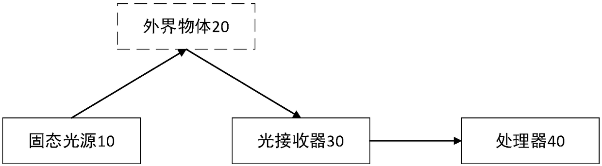
[0019] like figure 1 and figure 2 As shown, the present invention provides a preferred embodiment of a solid-state light source for lidar.

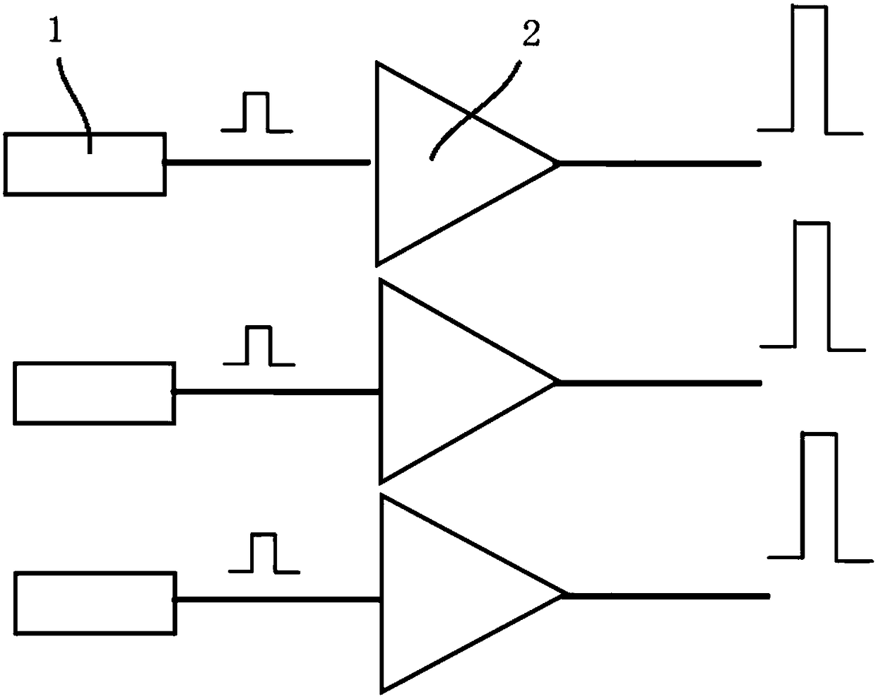
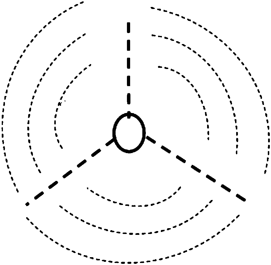
[0020] Specifically, a solid-state light source 10 for lidar, the solid-state light source 10 includes three optical transmitters 1 and optical fibers, and at least one optical amplifier 2, the optical transmitter 1 is fused to the optical amplifier 2 through an optical fiber, It is preferably arranged at the front end of the optical amplifier 2, for example, figure 1 The left side of the optical amplifier 2 is the front end, and the right side is the rear end. The optical transmitter 1 is a seed source with a wavelength within the c-band range and can generate continuous pulsed optical signals. The optical amplifier 2 is used to amplify the optical signal. refer to figure 2 , the emission angle...


PUM


Abstract

The invention relates to the field of radar devices, in particular to a solid-state light source of laser radar and the laser radar. The solid-state light source comprises three light emitters and optical fibers, and further comprises at least one light amplifier. The light emitters are fused on the light amplifiers through the optical fibers. Light signals emitted by the light amplifiers form angles of 120 degrees. The 360-degree scanning range is covered by the light emitters with different wavelengths, the synchronous working mode can be adopted, and the solid-state light source is suitablefor the field of automatic driving, 3D scanning and the like.

Description

technical field [0001] The invention relates to the field of radar devices, in particular to a solid-state light source of a laser radar and a laser radar. Background technique [0002] Radar detects the position, speed and other characteristic quantities of the target by emitting laser beams. Its working principle is to first transmit the detection laser beam to the target, and then compare the received signal reflected from the target with the transmitted signal, and perform appropriate processing. , you can get the relevant information of the target, such as target distance, azimuth, height, speed, attitude, and even shape and other parameters. [0003] At present, most laser radars adopt a mechanical scanning method, and the light source rotates 360 degrees with the mechanical device while emitting laser light. Long-term work will cause wear and tear on the mechanical structure, resulting in a reduction in the service life of the lidar. Contents of the invention [0...

Claims


Application Information

Patent Timeline
Patent Type & Authority Applications(China)
IPC IPC(8): G01S7/484
CPCG01S7/484
Inventor 鲁开源华一敏
Owner O NET COMM (SHENZHEN) LTD
Why Eureka
Try Eureka