Device for cooling battery mould by using flat heat pipes

A flat heat pipe and module technology, which is applied in secondary batteries, circuits, electrical components, etc., can solve problems such as unbalanced performance of battery modules, shortening the life of power battery systems, and excessive heat accumulation in batteries, achieving excellent performance. Thermally responsive properties, light weight, consistent results

Active Publication Date: 2018-09-21
NANCHANG HANGKONG UNIVERSITY
View PDF14 Cites 3 Cited by
  • Summary
  • Abstract
  • Description
  • Claims
  • Application Information

AI Technical Summary

Problems solved by technology

In essence, this patent mainly uses air-cooled heat dissipation combined with sheet-shaped heat pipe materials with stronger thermal conductivity to dissipate heat inside the battery box. It is mainly used in occasions where the number of battery cells is small. Too many, the heat accumulation rate of the battery is too fast, which will lead to the occurrence of thermal runaway inside the battery box
At present, in the field of new energy vehicles, the power source driving the car is a battery pack composed of hundreds of cells connected in series and parallel, and the space for the battery pack on the new energy vehicle is limited. In space, when the battery box is working, the uneven distribution of the temperature field inside the box for a long time will also cause the performance of each battery module and monomer to be unbalanced, especially the aging rate of the batteries distributed in the high temperature area will be significantly lower than that in the low temperature area. Partly, with the accumulation of time, the discretization of physical properties between different batteries becomes more and more obvious, which makes the consistency between batteries worse, and even premature failure occurs, shortening the life of the entire power battery system

Method used


Image

  • Device for cooling battery mould by using flat heat pipes
  • Device for cooling battery mould by using flat heat pipes
  • Device for cooling battery mould by using flat heat pipes

Examples


Embodiment Construction

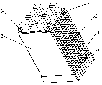
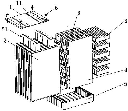
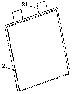
[0020] The present invention will be further described below in conjunction with drawings and embodiments. see Figure 1 to Figure 8 , a flat heat pipe used for heat dissipation of pouch battery modules, including a fixed support 5, a cell unit 2, a heat dissipation aluminum plate 4 and a connecting plate 1, the fixed support 5 is composed of a middle support block 51 and its The two ends of the side support block 52 are formed, the two ends of the middle support block 51 are provided with a T-shaped block 501, and a hollow groove is arranged in the T-shaped block 501; the two ends of the side support block 52 are provided with a protrusion 502, and the protrusion 502 Hollow grooves are also arranged inside, and slots 53 are formed between the middle support blocks 51 and between the side support blocks 52 at both ends; the hollow grooves in the T-shaped block 501 and the hollow grooves in the protrusions 502 are all filled with corresponding change material; the upper end of...


PUM


Abstract

The invention discloses a device for cooling a soft pack battery mould by using flat heat pipes. A fixed support seat is formed by middle support blocks and side support blocks, wherein the middle support blocks are sequentially arranged, and the side support blocks are respectively arranged at the two ends of the middle support blocks; T-shaped blocks are respectively arranged at the two ends ofthe middle support blocks, and a hollow groove is formed in each T-shaped block; convex blocks are respectively arranged at the two ends of the side support blocks, and hollow grooves are also respectively formed in the convex blocks; slots are respectively formed between the adjacent middle support blocks and between the middle support blocks and the side support blocks at the two ends; a connecting plate is provided with rabbets and is connected with pole lugs by means of the rabbets; a heat dissipation aluminum plate is installed between every two adjacent battery cell monomers; each heat dissipation aluminum plate is internally and symmetrically provided with flat holes, and the flat heat pipes are inserted into the flat holes. According to the device, the flat heat pipes are evenly distributed in the heat dissipation aluminum plates, and the advantages of thermal switching performance, excellent thermal response property, small volume, light weight, no power consumption and no noise of the flat heat pipes are combined; the device is rapider in module heat dissipation rate, higher in heat dissipation efficiency and better in module temperature field consistency.

Description

technical field [0001] This patent relates to the technical field of thermal management and heat dissipation of lithium-ion battery modules for new energy vehicles, in particular to a flat heat pipe cooling device for soft-pack battery modules. Background technique [0002] As the power source of pure electric vehicles, the power battery is a key link to improve vehicle performance and reduce costs. Its temperature characteristics directly affect the performance, life and durability of electric vehicles. When the heat generation rate of the battery module is greater than its module When the heat conduction rate is high, as the heat accumulates, it will affect the service life and stability of the electric vehicle battery, and even more seriously, it may cause deflagration and affect safety. [0003] Due to its low cost, the conventional air-cooled technology was first considered by battery thermal management designers. However, due to the limitation of the convective heat tr...

Claims


Application Information

Patent Timeline
Patent Type & Authority Applications(China)
IPC IPC(8): H01M10/613H01M10/625H01M10/647H01M10/653H01M10/6555H01M10/6557H01M10/6552
CPCH01M10/613H01M10/625H01M10/647H01M10/653H01M10/6552H01M10/6555H01M10/6557Y02E60/10
Inventor 李志农罗宗鸿卢祥军
Owner NANCHANG HANGKONG UNIVERSITY
Why Eureka
Try Eureka