Antenna and unmanned aerial vehicle
A technology for unmanned aerial vehicles and antennas, which is applied in the directions of aircraft, antennas, and antenna parts, etc., can solve the problems of low antenna efficiency, antenna resonance frequency shift, and antenna efficiency reduction, and achieve the effect of improving radiation efficiency.
- Summary
- Abstract
- Description
- Claims
- Application Information
AI Technical Summary
Problems solved by technology
Method used
Image
Examples
Embodiment 1
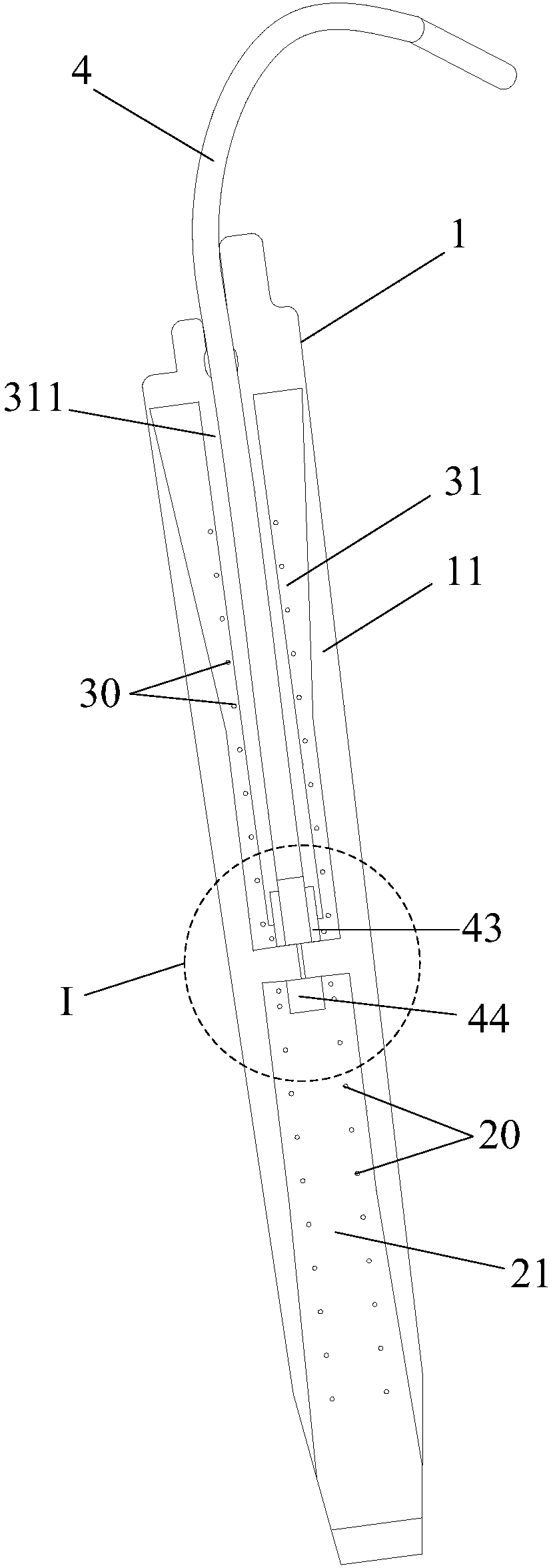
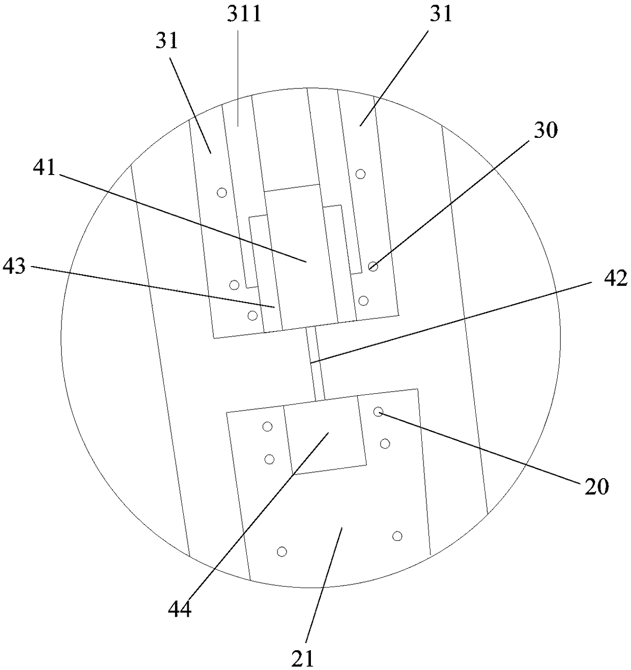
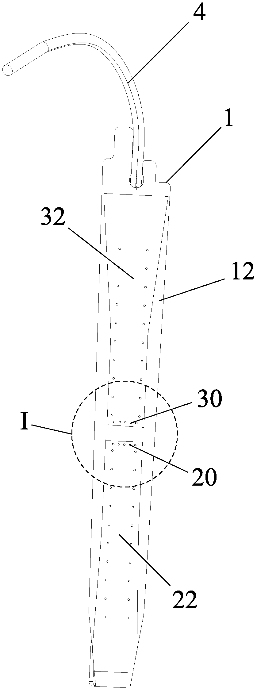
[0077] figure 1 It is a schematic structural diagram of the first surface of the antenna substrate provided by Embodiment 1 of the present invention. figure 2 for figure 1 The enlarged view of the structure at I. image 3 It is a schematic structural diagram of the second surface of the antenna substrate provided by Embodiment 1 of the present invention. Figure 4 for image 3 The enlarged view of the structure at I. Figure 5 It is a schematic diagram of the overall structure of the antenna provided by Embodiment 1 of the present invention. Figure 6 A schematic structural diagram of a guide plate of an antenna provided in Embodiment 1 of the present invention. refer to Figure 1 to Figure 6 As shown, the present invention provides an antenna. The antenna can be applied to unmanned aerial vehicles. When the antenna is applied on an unmanned aerial vehicle, the antenna is specifically installed outside the body of the unmanned aerial vehicle.
[0078] The antenna inc...
Embodiment 2
[0113] Figure 8 It is a schematic structural diagram of the first surface of the antenna substrate provided by Embodiment 2 of the present invention. Figure 9 for Figure 8 The enlarged view of the structure at I. Figure 10 A schematic structural diagram of the second surface of the antenna substrate provided for Embodiment 2 of the present invention. Figure 11 for Figure 10 The enlarged view of the structure at I. Figure 12 The standing wave parameter diagram of the antenna provided by Embodiment 2 of the present invention. refer to Figure 8 to Figure 12 As shown, this embodiment provides an antenna with another structure. On the basis of the antenna provided by Embodiment 1, this embodiment further adds a second radiation unit and a second antenna ground unit on the substrate 1 .
[0114] Wherein, the second radiating unit specifically includes: the third radiating part 51 arranged on the first surface 11 of the substrate 1 and electrically connected to the firs...
Embodiment 3
[0134] Figure 13 It is a schematic structural diagram of the unmanned aerial vehicle provided by Embodiment 3 of the present invention. Figure 14 The side view of the unmanned aerial vehicle provided for the third embodiment of the present invention. combine Figure 1 to Figure 14 As shown, this embodiment provides an unmanned aerial vehicle, which includes a body 81, a power unit, and an antenna.
[0135] Specifically, the machine body 81 may have a machine arm 82 , the power device may be disposed at an end of the machine arm 82 , and the antenna is installed outside the machine body 81 .
[0136] Wherein, the power device may specifically include: a rotor (not shown in the figure) and a motor 83, and the motor 83 is used to drive the rotor to rotate, thereby providing power for the flight of the unmanned aerial vehicle. In this embodiment, the unmanned aerial vehicle is specifically a four-rotor unmanned aerial vehicle. It should be noted that the unmanned aerial vehic...
PUM
 Abstract
Description
Claims
Application Information
 - R&D
- Intellectual Property
- Life Sciences
- Materials
- Tech Scout
- Unparalleled Data Quality
- Higher Quality Content
- 60% Fewer Hallucinations
Browse by: Latest US Patents, China's latest patents, Technical Efficacy Thesaurus, Application Domain, Technology Topic, Popular Technical Reports.
© 2025 PatSnap. All rights reserved.Legal|Privacy policy|Modern Slavery Act Transparency Statement|Sitemap|About US| Contact US: help@patsnap.com


