A system and method for leak monitoring of fuel evaporation system

A technology of fuel evaporation system and leak hole, which is applied in the direction of charging system, engine components, machine/engine, etc., can solve oil and gas leakage, and it is impossible to distinguish whether it is only the pressure curve under the reference hole or contains and weakens the airtightness of the fuel evaporation system In order to achieve the effect of reducing pipeline disconnection and improving accuracy

Active Publication Date: 2019-11-26
扬州华光新材料股份有限公司
View PDF6 Cites 2 Cited by
  • Summary
  • Abstract
  • Description
  • Claims
  • Application Information

AI Technical Summary

Problems solved by technology

U.S. Patent (US20150090006A1) proposes a leak monitoring method that combines pressurization and decompression methods. The pressurization method is used first because the monitoring of the pressurization method is more accurate than the decompression method. By monitoring the existence of leak holes and the approximate Then use the decompression method with a slightly lower accuracy to monitor the diameter of the cumulative leak hole detected by the pressurization method; however, if the pressurization method is used for leak monitoring, the oil and gas in the fuel evaporation system will overflow through the leak hole , which weakens the airtightness of the fuel evaporation system; in addition, the cumulative leakage hole diameter judging module used in this patent can only judge the cumulative leakage hole diameter of about 0.5mm
The Chinese patent (CN107152354A) sets the pressure sensor in the cumulative leakage hole diameter judging module. First, the vacuum pump is used to evacuate the evaporation system, and the reference pressure curve under the reference hole is measured. The pressure curve when there is a leak hole is corrected by using an oxygen sensor; however, since the sensor is set in the cumulative leak hole diameter judgment module of the evaporation system, when the module is switched to the reference hole, the measured pressure curve cannot be distinguished. The pressure curve under the reference hole still includes the pressure curve of the leak hole of the fuel evaporation system, that is, when the module is switched to the reference hole, the pressure curve needs to be processed with the pressure curve when only the leak hole is used.
In addition, when the cumulative leakage hole diameter judgment module is not operating, if the fuel tank is pressurized, then the fuel gas in the fuel tank is likely to leak from the reference hole of the module

Method used


Image

  • A system and method for leak monitoring of fuel evaporation system
  • A system and method for leak monitoring of fuel evaporation system
  • A system and method for leak monitoring of fuel evaporation system

Examples


Embodiment Construction

[0018] The present invention will be described in further detail below in conjunction with the accompanying drawings and specific embodiments.

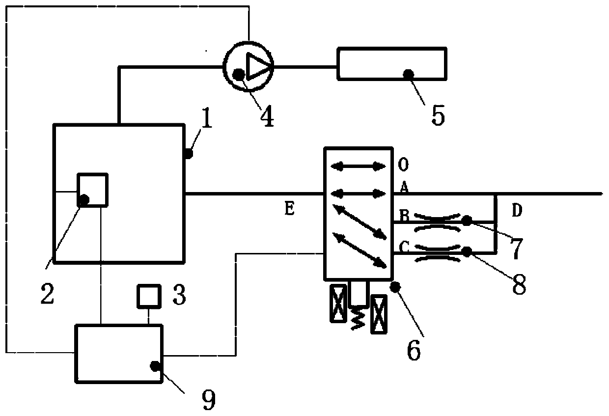
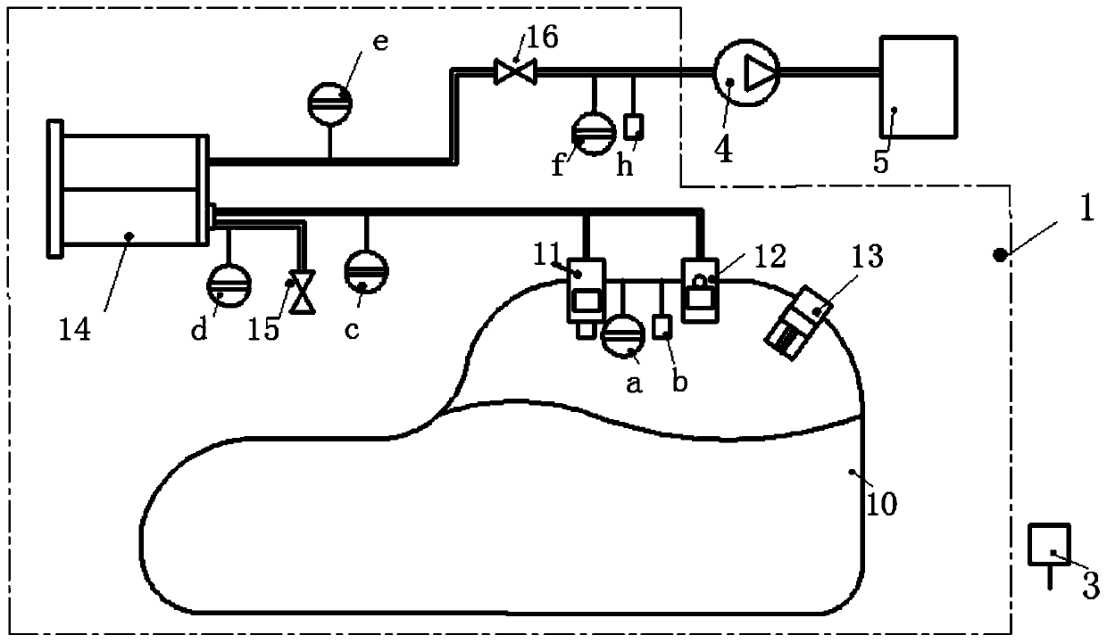
[0019] See attached figure 1 , the system used for monitoring the leakage of the fuel evaporation system includes a fuel evaporation system 1, sensors are arranged in each section of the fuel evaporation system 1, including a pressure and temperature sensor group 2 installed in the fuel evaporation system 1 and a sensor set installed outside the fuel evaporation system 1 The temperature sensor 3 and the vacuum pump 4 are located between the fuel evaporation system 1 and the intake manifold 5. The reversing valve 6 is installed on the pipe outside the fuel evaporation system 1. The reversing valve 6 is provided with four channels: fuel evaporation system leakage hole Channel A, channel B installed with 0.5mm reference hole 7, channel C installed with 1mm reference hole 8, and cut-off channel O, the reversing valve 6 is provided with a ...


PUM


Abstract

The invention discloses a system and a method for monitoring the leakage of a fuel evaporation system. The system for monitoring the leakage of the fuel evaporation system comprises a module used forjudging whether the diameter phi of an accumulative leakage hole is less than 0.5 mm, or more than 0.5 mm and less than 1 mm, or more than 1 mm; the judging module comprises a vacuum pump, a pressureand temperature sensor group installed in the evaporation system, a temperature sensor installed outside the evaporation system, a controller, and a reversing valve having a closing function, the reversing valve comprises a channel communicated with the fuel evaporation system, a channel provided with a 0.5 mm datum hole, and a channel provided with 1 mm datum hole. The method for monitoring the leakage of the fuel evaporation system comprises three monitoring stages: firstly, a preparatory stage for judging whether the leakage monitoring meets the molecular counting condition by the evaporation system; second, a monitoring stage used for judging whether a pipeline is disconnected, whether a carbon tank is blocked and whether an oil tank cover falls off; and thirdly, a judging stage used for judging the diameter of the accumulative leakage hole through the judging module and the equation.

Description

technical field [0001] The invention relates to the technical field of leakage monitoring of a car fuel evaporation system, in particular to a system and method for monitoring the leakage of a fuel evaporation system. Background technique [0002] Regarding the relevant research on the leakage monitoring of the fuel evaporation system, such as the United States patent (US05637788), it is proposed to close all the valves in the fuel evaporation system, monitor whether the pressure in the fuel tank rises, and then open the flow control valve to monitor whether the pressure in the fuel tank drops. Determine if the fuel tank cap is open. But if the pipeline in the fuel evaporation system is disconnected, the pressure in the fuel tank will not rise when the valves are fully closed, and the pressure will not drop when the flow control valve is opened, and the fuel tank cap test will fail. U.S. Patent (US20150090006A1) proposes a leak monitoring method that combines pressurization...

Claims


Application Information

Patent Timeline
Patent Type & Authority Patents(China)
IPC IPC(8): F02M25/08
CPCF02M25/0809
Inventor 何仁方妍月
Owner 扬州华光新材料股份有限公司
Why Eureka
Try Eureka