High pressure heat insulation gas storage pumping compressed air energy storage system

A compressed air energy storage and gas storage technology, which is applied in the fields of hydropower generation, liquid variable capacity machinery, pump devices, etc., can solve the problems of high investment cost of high-pressure gas storage tanks, cavitation of turbine blades, and reduced operating economy, etc. Achieve the effect of shortening the recovery period, reducing the contact area, improving the energy storage density and operating efficiency

Active Publication Date: 2018-09-25
XI AN JIAOTONG UNIV
View PDF7 Cites 25 Cited by
  • Summary
  • Abstract
  • Description
  • Claims
  • Application Information

AI Technical Summary

Problems solved by technology

During the energy storage process of the water-gas co-containment cabin electric energy storage system using a high-pressure gas storage tank with constant pressure, the pressure in the high-pressure gas storage tank continues to rise, the back pressure of the supercharger increases, and its flow rate changes continuously causing water Pressure fluctuations in the air-contained cabin; under high pressure, the solubility of the gas in th

Method used


Image

  • High pressure heat insulation gas storage pumping compressed air energy storage system
  • High pressure heat insulation gas storage pumping compressed air energy storage system
  • High pressure heat insulation gas storage pumping compressed air energy storage system

Examples


Embodiment Construction

[0037] The present invention is described in further detail below in conjunction with accompanying drawing:

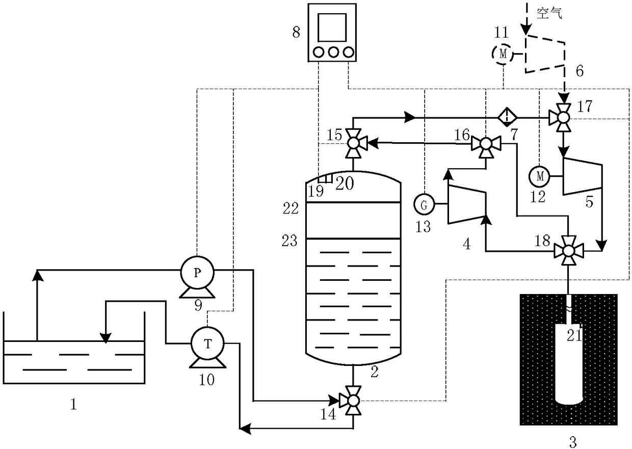
[0038] Such as Figure 1 to Figure 7 As shown, a high-pressure adiabatic gas storage pumping compressed air energy storage system of the present invention includes a water storage tank 1, a water pump unit 9, a water turbine unit 10, a water-gas co-containment cabin 2, a hollow steel plate 23, a gas storage shaft 3, a pressurized Machine 5, turbine 4, water-gas separator 7;

[0039] The water inlet and the water outlet of the water-air co-containment cabin 2 are the same water inlet and outlet, and the reservoir 1 is connected to the water-gas co-containment cabin 2 bottom water inlet and outlet through the first three-way valve 14 and the water pump unit 9. At the same time, the water-gas co-containment cabin The water inlet and outlet at the bottom of the cabin 2 are connected to the reservoir 1 through the first three-way valve 14 and the water turbine unit 10; Th...


PUM


Abstract

The invention discloses a high pressure heat insulation gas storage pumping compressed air energy storage system. Air in a water-gas common-cabin passes a supercharger and then directly enters a gas storage vertical shaft, and pressure of gas in the water-gas common-cabin passes is kept stable and unchanged. Potential energy and heat of compressed air are stored at the same time because of the thermal storage effect of the gas storage vertical shaft. At the stage of energy releasing, output electric energy of the system comprises the following two parts: for one part, high pressure air with certain temperature in the vertical shaft enters a turbine to do work through expansion; for the other part, water in the water-gas common-cabin pushes the turbine to generate electric energy, and the energy density and operating efficiency of the system are improved. As a heat insulating layer is arranged outside the gas storage vertical shaft, the air is high in temperature and flows through the turbine and is expanded, then the temperature is reduced, the fact that the temperature in the water-gas common-cabin is low is guaranteed, and damage to the turbine caused by temperature rise of wateris avoided. The system stores high pressure air through the gas storage vertical shaft, greatly reduces the investment cost of a high pressure container, shortens the payback time, and improves the operating economy.

Description

technical field [0001] The invention relates to the field of electric energy physical storage, in particular to a high-pressure adiabatic gas storage pumped compressed air energy storage system. Background technique [0002] With the increasingly prominent energy and environmental problems, renewable energy such as wind energy and solar energy has received more and more attention. development poses enormous challenges. As a transitional system between the power plant and the grid, the energy storage system can effectively solve the grid connection problem of renewable energy. In addition, the energy storage system can also smooth the load fluctuation of the power grid and improve the security and controllability of the power grid. Among the existing energy storage methods, due to the limitation of energy storage scale, discharge time, technology maturity and other factors, only compressed air energy storage and pumped hydro storage can be applied on a large scale. [0003...

Claims


Application Information

Patent Timeline
IPC IPC(8): F03B13/06F01D15/10F04B41/02F04B41/06
CPCF01D15/10F03B13/06F04B41/02F04B41/06Y02E10/20Y02E60/16
Inventor 王焕然张淑宇李瑞雄李丞宸严凯刘明明
Owner XI AN JIAOTONG UNIV
Why Eureka
Try Eureka