Garbage incineration system

A waste incineration and incinerator technology, applied in the direction of incinerators, combustion methods, combustion types, etc., can solve the problems of large area, high cost, unfavorable incineration, etc., and achieve the effect of reducing the occupied area and reducing the cost of use

Pending Publication Date: 2018-09-25
湖州高盛环保科技有限公司
View PDF10 Cites 3 Cited by
  • Summary
  • Abstract
  • Description
  • Claims
  • Application Information

AI Technical Summary

Problems solved by technology

However, in the prior art, the dispersing machine and the drying machine are connected separately to achieve dispersing and drying respectively, which not only occupies a large area, but also costs a lot; when performing dispersing and drying, the effect is not very good. Well, it's not good for the garbage to burn in the incinerator

Method used


Image

  • Garbage incineration system
  • Garbage incineration system
  • Garbage incineration system

Examples


Embodiment 1

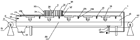
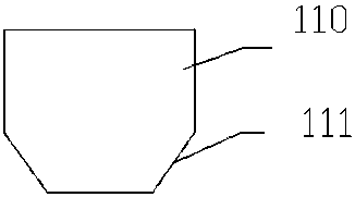
[0043] A garbage incineration system, including an incinerator and an integrated device for breaking up and drying, characterized in that: the integrated device for breaking up and drying includes a casing 1 and a conveyor 2, the casing 1 is a closed shell, and the casing 1 Including the inlet section 10 and the outlet section 11, the cross-sectional area of ​​the outlet section 11 is larger than the cross-sectional area of ​​the inlet section 10, the end of the inlet section 10 is provided with a feed port, the end of the outlet section 11 is provided with an outlet, and the bottom of the inlet section 10 A hot air inlet 12 is provided, a hot air outlet 13 is provided on the top of the outlet section 11, and a discharge port 14 is provided at the bottom of the outlet section 11. A plurality of blowers 15 and a plurality of breakers 16 are installed on the top, the blowers 15 and the breakers 16 are arranged at intervals, the distance between the two sides of the conveyor belt ...

Embodiment 2

[0051] On the basis of Embodiment 1, the hot air inlet 12 of the casing 1 is connected to the hot air inlet pipe 120, the hot air outlet 13 is connected to the hot air outlet pipe 130, and a heat exchanger 3 is installed on the top of the casing 1, and the heat exchanger 3 includes a casing 30 and the heat exchange coil 31, the heat exchange coil 31 is installed in the housing 30, the housing 30 is provided with a hot water inlet 32, a hot water outlet 33, an air inlet 34 and an air outlet 35, the heat exchange coil 31 One end is connected with the hot water inlet 32, the other end is connected with the hot water outlet 33, the hot air outlet pipe 130 is connected with the air inlet 34, the hot air inlet pipe 120 is connected with the air outlet 35, and the end of the outlet section 11 is also installed There are hair dryers 15.

Embodiment 3

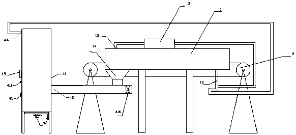
[0053] On the basis of Embodiment 1, an air blowing device is installed at the inner bottom of the body of furnace 41. The air blowing device includes an air blowing pipe 414, an air pipe 415 and a blower 416. There are multiple air blowing pipes 414, and they are installed on the air pipe 415. Air pipe 414 is positioned at the inner bottom of body of heater 41, and air pipe 415 is positioned at outer bottom of body of heater 41.

[0054] The air blowing tube 414 includes an inner tube 417, an outer tube 418 and a disc 419. The disc 419 passes through the inner tube 417 and is welded on the inner tube 417. The outer tube 418 covers the inner tube 417, and the inner tube 417 and the inner tube 417 The air pipe 415 is connected, the outer pipe 418 is a truncated cone, and the inner pipe 417 is a seamless steel pipe with two openings. The side of the outer pipe 418 is provided with an air blowing hole 420. The air blowing hole 420 is obliquely arranged on the outer pipe 418. The a...


PUM


Abstract

The invention discloses a garbage incineration system which comprises an incineration furnace and a scattering and drying integral device, wherein the scattering and drying integral device comprises ashell and a conveying machine; a plurality of air blowers and scattering machines are mounted at the top of the shell; the air blowers and the scattering machines are arranged at intervals; the distance between both sides of a conveyer belt of the conveying machine and a shell wall of an inlet section is 0-5mm; the distance between both sides of the conveyer belt of the conveying machine and theshell wall of an outlet section is 20cm or above; the incineration furnace comprises a furnace body; a garbage feeding hole is formed in the right side of the furnace body; an ash outlet is formed inthe bottom of the furnace body; an exhaust hole is formed in the top of the furnace body; a gas feeding hole is formed in the right side of the furnace body; a hot air inlet is connected with the exhaust hole in the incineration furnace; the garbage feeding hole of the incineration furnace is connected with the discharge hole through a pipeline; an air blower is mounted on the right side of the discharge hole. When garbage is incinerated by using the garbage incineration system, the garbage is scattered when being incinerated, so that not only is a good scattering and incineration function achieved, but also a floor space is reduced, the cost is reduced, heat can be circulated and recycled, and the energy consumption can be reduced.

Description

technical field [0001] The invention relates to environmental protection treatment equipment, in particular to equipment used for incinerating garbage. Background technique [0002] The disposal methods of domestic waste include landfill and incineration. The advantage of landfill treatment is that it is simple and the treatment cost is low. The disadvantage is that it breeds bacteria, mosquitoes and flies, and pollutes groundwater. Materials such as plastic bags are difficult to explain and cause soil damage. Seriously affect the surrounding environment; the advantage of incineration is that the garbage is directly burned, and the treatment method is relatively simple, but the cost is higher than that of landfill, and it will generate waste gas and pollute the atmosphere. Whether it is landfill or incineration, it is a common way to deal with domestic waste at present. After the domestic garbage is collected, in order to facilitate transportation, the garbage will be squee...

Claims


Application Information

Patent Timeline
Patent Type & Authority Applications(China)
IPC IPC(8): F23G5/02F23G5/04F23G5/44F23G5/46
CPCF23G5/02F23G5/04F23G5/44F23G5/444F23G5/46
Inventor 俞国京
Owner 湖州高盛环保科技有限公司
Why Eureka
Try Eureka