A top battery automatic replacement and fixing device for a movable platform

A mobile platform and automatic replacement technology, applied in the direction of battery pack parts, circuits, electrical components, etc., can solve the problems of limitation, high positioning accuracy requirements, and platform space occupation, and achieve the elimination of size constraints, fast and reliable replacement, System works reliably

Active Publication Date: 2020-12-04
江苏洋口港建设发展集团有限公司
View PDF5 Cites 0 Cited by
  • Summary
  • Abstract
  • Description
  • Claims
  • Application Information

AI Technical Summary

Problems solved by technology

Later, some patent documents proposed to replace the battery to replenish energy, which greatly shortened the time for the platform to replenish energy. However, the battery replacement mechanism used in this document requires high positioning accuracy during work, and occupies the platform. A large amount of space makes it difficult for the equipment to be installed or squeezed, and the potential of the platform cannot be maximized. Therefore, a new battery replacement mechanism is needed to realize the action of replacing the battery without occupying the space of the rest of the equipment as much as possible.
[0003] Patent No. 2015106159143 A battery replacement, fixation, and support mechanism for a battery-replaceable mobile platform proposes a fast and reliable battery replacement device on the side, which achieves better space utilization, but found that side replacement The battery solution is limited by the wheelbase of the front and rear moving wheels of the mobile platform, and the size and length of the battery are limited. At the same time, because it is installed on the side, the height of the battery is limited by the height of the moving wheels, so a new design is required to solve the problem of battery size. restricted question

Method used


Image

  • A top battery automatic replacement and fixing device for a movable platform
  • A top battery automatic replacement and fixing device for a movable platform
  • A top battery automatic replacement and fixing device for a movable platform

Examples


Embodiment Construction

[0043] The following will clearly and completely describe the technical solutions in the embodiments of the present invention with reference to the accompanying drawings in the embodiments of the present invention. Obviously, the described embodiments are only some of the embodiments of the present invention, not all of them. Based on the embodiments of the present invention, all other embodiments obtained by persons of ordinary skill in the art without creative efforts fall within the protection scope of the present invention.

[0044] The invention discovers a device with high space utilization rate, which installs and fixes the battery on the top of the mobile platform, and realizes fast and reliable replacement of the battery at the same time.

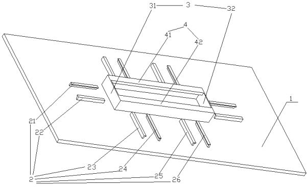
[0045] Such as figure 1 As shown, it is a perspective view of the mobile platform of the present invention. The main body of the mobile platform is a rectangular flat plate 1, which is a simplified intelligent patrol car or other w...


PUM


Abstract

An automatic battery replacement and fixing device on the top of a movable platform aims to design a device with high space utilization, install and fix the battery on the top of the mobile platform, and at the same time realize fast and reliable replacement of the battery. It is composed of mobile platform, slider, drive motor, drive gear, bar gear, photoelectric pair tube, support plate, battery bracket, gripper and battery. When the electric energy of the battery is about to be used up by the mobile platform, the mobile platform returns to the position of the battery replacement pile, eliminates battery constraints, and holds up the battery, making it easier for the mechanism of the battery replacement pile to grab the battery. After the mechanism of the battery replacement pile takes away the battery that needs to be charged and puts down the new battery again, each gripper forms a form of embracing the battery, so that the battery is fixed in an ideal position. It achieves a high space utilization rate, installs and fixes the battery on the top of the mobile platform, and realizes fast and reliable replacement of the battery at the same time, making the system work more reliable and stable.

Description

technical field [0001] The invention belongs to an automatic replacement and fixing device for battery components of a mobile platform, in particular to a battery replacement and fixing device for a mobile platform with battery components placed on the top. Background technique [0002] As the power supply platform is applied in many fields, the advantages of the power supply platform can be brought into play. At the same time, some defects of the power supply platform are gradually exposed. The low energy storage density of the battery is a typical defect. In order to overcome this defect, The technicians have adopted the means of automatic return charging and multi-platform alternate relay work to achieve the purpose of long-term uninterrupted work. Later, some patent documents proposed to replace the battery to replenish energy, which greatly shortened the time for the platform to replenish energy. However, the battery replacement mechanism used in this document requires ...

Claims


Application Information

Patent Timeline
Patent Type & Authority Patents(China)
IPC IPC(8): H01M2/10H01M50/256
CPCH01M50/256Y02E60/10
Inventor 谷敏俊其他发明人请求不公开姓名
Owner 江苏洋口港建设发展集团有限公司
Why Eureka
Try Eureka