Constant-temperature stamping equipment with automatic discharging function

A technology of automatic discharging and stamping equipment, applied in safety equipment, metal processing equipment, non-rotational vibration suppression, etc., can solve the problems of restricting large-scale popularization and application, low transmission efficiency, high use cost, and improve shock absorption performance and The effect of service life, improving stamping quality, and continuous safe production

Inactive Publication Date: 2018-09-28
YANCHENG CHUANLIU AUTO PARTS CO LTD
View PDF5 Cites 9 Cited by
  • Summary
  • Abstract
  • Description
  • Claims
  • Application Information

AI Technical Summary

Problems solved by technology

At present, the power of traditional stamping machine tools in my country comes from rotary motors, which require a series of conversion mechanisms to convert rotary motion into reciprocating linear motion. In order to obtain a large enough punching force, a large energy storage flywheel is also required, so there are many intermediate parts. , low transmission efficiency, complex structure, bulky volume, poor shockproof effect, poor stability, high noise, short service life, and existing stamping equipment, high-speed stamping dies are equipped with cooling pipelines inside, and cooling pipelines circulate in the cooling pipelines. There is a temperature sensor inside the high-speed stamping die to monitor the internal temperature of the high-speed stamping die, and the control device controls the infusion pump to adjust the flow of coolant according to the temperature information of the sensor. This product ensures stamping accuracy and production efficiency. It can also reduce the deformation and damage of the mold and improve the service life, but due to the use of automatic control, the cost of use is high, which limits its large-scale application

Method used


Image

  • Constant-temperature stamping equipment with automatic discharging function

Examples


Embodiment Construction

[0014] The following will clearly and completely describe the technical solutions in the embodiments of the present invention with reference to the accompanying drawings in the embodiments of the present invention. Obviously, the described embodiments are only some, not all, embodiments of the present invention. Based on the embodiments of the present invention, all other embodiments obtained by persons of ordinary skill in the art without making creative efforts belong to the protection scope of the present invention.

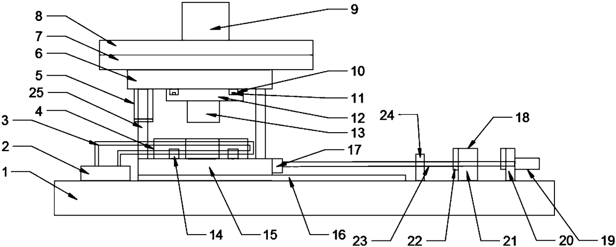
[0015] see figure 1 , in an embodiment of the present invention, a constant temperature stamping equipment for automatic discharge includes a base 1, a cooling device 2, an upper die assembly, a lower die assembly and a discharge device 18, and the upper die assembly includes an upper die connection Plate 6, upper die backing plate 7, upper die base 8, punch 13, described upper die base 8, upper die backing plate 7, upper die connecting plate 6 are fixedly con...


PUM


Abstract

The invention discloses constant-temperature stamping equipment with an automatic discharging function. The constant-temperature stamping equipment comprises a base, a cooling device, an upper die assembly, a lower die assembly and a discharging device. The upper die assembly comprises an upper die connecting plate, an upper die base plate, an upper die seat and a male die. A hydraulic cylinder isarranged on the upper die seat, and a guide rail is arranged on the base. The lower die assembly comprises a lower die sliding block and a lower die fixing plate, and the lower die fixing plate is arranged on the guide rail. A female die is arranged on the position, corresponding to the male die, of the lower die sliding block. The discharging device is mounted on one side of the base, and the cooling device is connected with a circuitous pipeline which is arranged in the lower die sliding block. A stroke protecting mechanism is arranged between the male die and the female die. The female diecan keep the appropriate temperature range, thus the stamping quality is improved, and the service life of the equipment is prolonged; and the pneumatic mode is adopted, noise is small, discharging is convenient, and it is guaranteed that the equipment operates stably.

Description

technical field [0001] The invention relates to a stamping equipment, in particular to a constant temperature stamping equipment with automatic discharge. Background technique [0002] Stamping equipment has been widely used in the processing of hardware parts in the fields of electronics, communications, home appliances, furniture and transportation. Its advantage lies in the efficient and stable large-scale production by matching different molds. At present, the power of traditional stamping machine tools in my country comes from rotary motors, which require a series of conversion mechanisms to convert rotary motion into reciprocating linear motion. In order to obtain a large enough punching force, a large energy storage flywheel is also required, so there are many intermediate parts. , low transmission efficiency, complex structure, bulky volume, poor shockproof effect, poor stability, high noise, short service life, and existing stamping equipment, high-speed stamping die...

Claims


Application Information

Patent Timeline
Patent Type & Authority Applications(China)
IPC IPC(8): B21D22/00B21D37/10B21D37/12B21D37/16B21D55/00B21D45/06F16F15/08
CPCB21D22/00B21D37/10B21D37/12B21D37/16B21D45/06B21D55/00F16F15/08
Inventor 温启浩
Owner YANCHENG CHUANLIU AUTO PARTS CO LTD
Why Eureka
Try Eureka