Electroplating product separation device and electroplating product separation method
A separation device and product technology, applied in the field of electroplating product separation device, can solve the problems of material performance decline, secondary pollution, etc., and achieve the effects of improving performance, no secondary waste, and avoiding serious damage
- Summary
- Abstract
- Description
- Claims
- Application Information
AI Technical Summary
Problems solved by technology
Method used
Image
Examples
Embodiment 1
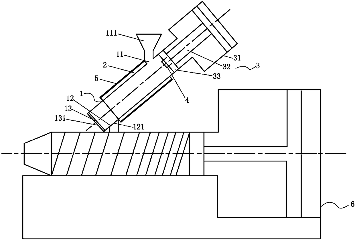
[0056] like figure 1 As shown, an electroplating product separation device includes a barrel 1, a heating mechanism 2, an extrusion mechanism 3, a temperature sensor 4 and a control unit,
[0057] The barrel 1 is provided with a feed port 11 and a discharge port 12, the feed port 11 and the discharge port 12 are arranged oppositely,
[0058] The heating mechanism 2, the extruding mechanism 3 and the temperature sensor 4 are respectively connected to the control unit, and the heating mechanism 2 is arranged on the wall of the barrel 1 for heating the barrel The material to be separated in 1; the extruding mechanism 3 is arranged at one end of the feeding port 11 of the barrel 1, and is used to apply pressure to the material to be separated after melting and extrude the molten material from the discharge port 12. thing;
[0059] The temperature sensor 4 is arranged in the barrel 1 , and the control unit receives the signal of the temperature sensor 4 to control the heating tem...
Embodiment 2
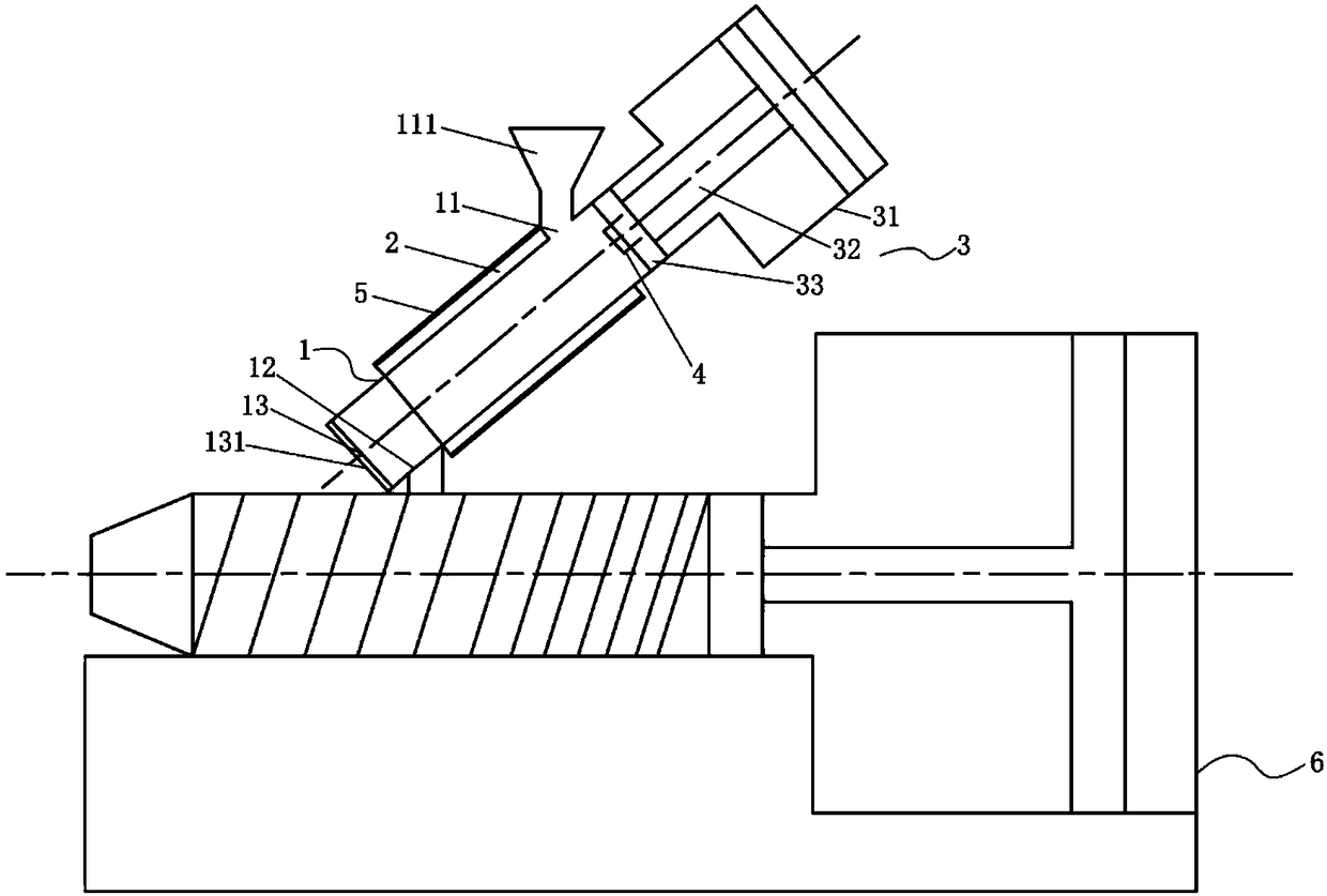
[0082] like figure 2 As shown, an electroplating product separation device includes a barrel 1, a heating mechanism 2, an extrusion mechanism 3, a temperature sensor 4 and a control unit,
[0083] The barrel 1 is provided with a feed port 11 and a discharge port 12, the feed port 11 and the discharge port 12 are arranged oppositely,
[0084] The heating mechanism 2, the extruding mechanism 3 and the temperature sensor 4 are respectively connected to the control unit, and the heating mechanism 2 is arranged on the wall of the barrel 1 for heating the barrel The material to be separated in 1; the extruding mechanism 3 is arranged at one end of the feeding port 11 of the barrel 1, and is used to apply pressure to the material to be separated after melting and extrude the molten material from the discharge port 12. thing;
[0085] The temperature sensor 4 is arranged in the barrel 1 , and the control unit receives the signal of the temperature sensor 4 to control the heating te...
Embodiment 3
[0108] A method for separating electroplating products using the separation device described above, comprising the following steps:
[0109] S1. Coarsely crush the electroplated product in a crusher to obtain the material to be separated;
[0110] S2. Add the material to be separated and the filler into the barrel 1 through the hopper 111;
[0111] S3. Start the heating mechanism 2 to heat the material to be separated in the barrel 1 to a set temperature;
[0112] S4. After the substrate layer of the material to be separated reaches a molten state, start the extrusion mechanism 3 to extrude the melt from the discharge port 12;
[0113] S5. When the extrusion pressure reaches the set value, open the slag discharge port 13 to discharge the residue.
[0114] In step S1, the volume of the material to be separated added into the barrel 1 does not exceed 4 / 5 of the volume of the barrel 1 .
[0115] In step S2, the filler includes a lubricant and a catalyst, and the lubricant is u...
PUM
 Abstract
Description
Claims
Application Information
 - R&D
- Intellectual Property
- Life Sciences
- Materials
- Tech Scout
- Unparalleled Data Quality
- Higher Quality Content
- 60% Fewer Hallucinations
Browse by: Latest US Patents, China's latest patents, Technical Efficacy Thesaurus, Application Domain, Technology Topic, Popular Technical Reports.
© 2025 PatSnap. All rights reserved.Legal|Privacy policy|Modern Slavery Act Transparency Statement|Sitemap|About US| Contact US: help@patsnap.com


