Spatial positioning directing actuation system, and 3D printing machine and method

A space positioning and actuation system technology, applied in the fields of medical treatment and 3D printing, can solve problems such as mechanical structure accumulation errors, major surgical wounds, long action stroke errors, etc., and achieve the effect of small size, accurate positioning, and wide range of use

Active Publication Date: 2018-09-28
杨斌堂
View PDF7 Cites 2 Cited by
  • Summary
  • Abstract
  • Description
  • Claims
  • Application Information

AI Technical Summary

Problems solved by technology

[0003] However, in the existing technology, 3D printing is mostly used for printing in exposed spaces, and there is a lack of a structure that can puncture into the structure and then print. For example, the local filling of tissues such as internal bones of organisms often results in large surgical wounds.
In addition, most of the current 3D printers are installed on a fixed base. During the positioning process, on the one hand, there will be a cumulative error due to the excessive mechanical structure, and on the other hand, a large error will be generated due to the long movement stroke.

Method used


Image

  • Spatial positioning directing actuation system, and 3D printing machine and method
  • Spatial positioning directing actuation system, and 3D printing machine and method
  • Spatial positioning directing actuation system, and 3D printing machine and method

Examples


Embodiment 1

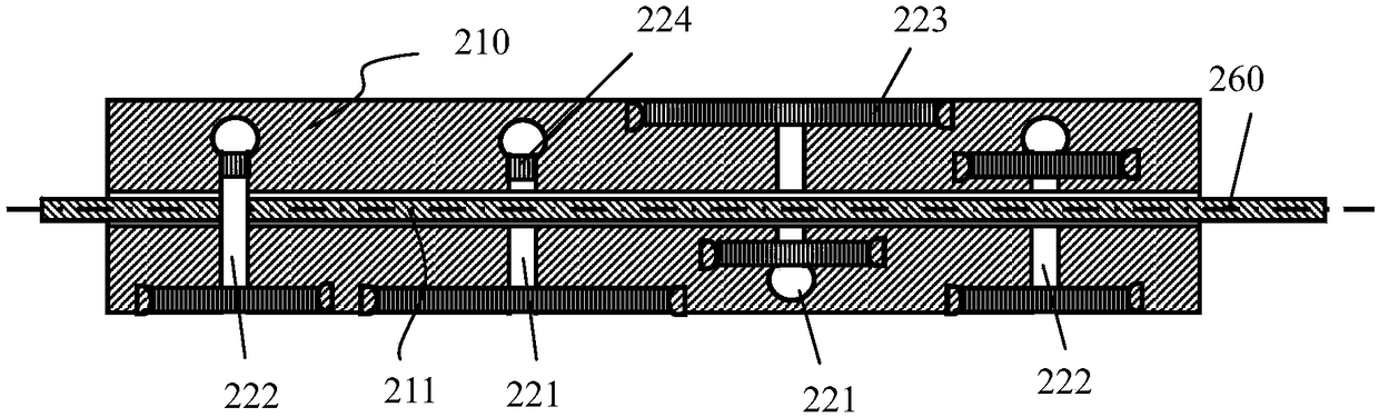
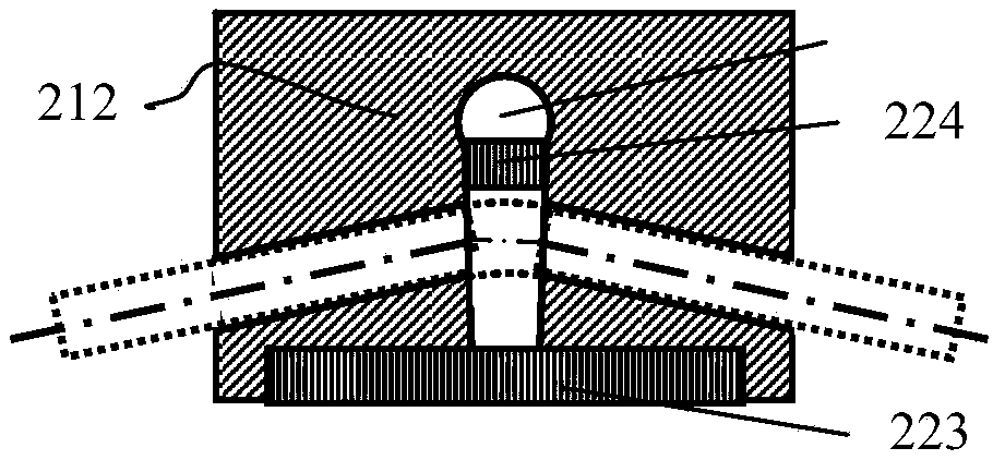
[0094] Such as figure 2 As shown, in this embodiment, the driving part 213 and the clamping part 212 are an integrally formed structure, and the driving part 213 includes one or more driving groups, and the driving group includes opposite slot positions in the radial direction. The two driving slots 221 , the clamping portion 212 includes two clamping slots 222 with the same notch positions in the radial direction, and the two clamping slots 222 are respectively located at both ends of the driving portion 213 along the axial direction. Preferably, the clamping groove 222 is not limited to the above-mentioned arrangement position, and can also be located at other positions, for example, between a plurality of driving groups and the like. When the clamping driver 210 is stretched or compressed, the groove walls of the single driving groove 221 and the groove walls of the single clamping groove 222 will move away from or approach each other, so that the inner diameter of the pas...

Embodiment 2

[0097] This embodiment is a modification of the structure provided in Embodiment 1. Such as Figure 7 As shown, in this embodiment, the clamping part 212 and the driving part 213 are obtained by assembling, including two clamping parts 212 respectively arranged at both ends of the driving part 213 along the axial direction, and the clamping part 212 can be directly tightened. It is fixedly installed on the driving part 213, and can also be indirectly fastened and installed on the driving part 213 through other structures, such as an outer sleeve, etc.

[0098] Such as Figure 5 , Figure 6 As shown, in this embodiment, the clamping portion 212 includes a clamping box 231 , an engaging member 232 , an opening and closing elastic member, and an opening and closing switch 235 . One or more tapered holes are arranged in the clamping box 231, and the engaging member 232 is installed in the tapered holes. Such as Figure 5 As shown, in the locked state, the moving part 260 and ...

Embodiment 3

[0101] This embodiment is a modification of the structure provided in Embodiment 2. Such as Figure 8 , Figure 9 As shown, the on-off switch 235 has an electromagnet 241 structure with a mandrel 242, and the mandrel 242 is a magnet structure and is connected with the first elastic member 233, and the core is driven by controlling the power on and off of the electromagnet 241. The up and down movement of the shaft 242 further drives the deformation of the first elastic member 233 to complete the movement conversion of the engaging member 232 between the unlocked position and the locked position. preferably as Figure 10 , Figure 11 As shown, the opening and closing switch 235 is an electromagnet 241 structure without a mandrel 242, and the first elastic member 233 itself is a magnet, which directly attracts or releases the first elastic member 233 through a magnetic field to complete the alignment of the engaging member 232. drive. Preferably, as Figure 12 , Figure 13 ...


PUM


Abstract

The invention provides a spatial positioning directing actuation system, and further provides a 3D printing machine comprising the spatial positioning directing actuation system and a 3D printing method. The spatial positioning directing actuation system comprises a supporting platform (100) and a linear feeding structure. The linear feeding structure comprises a clamping driving piece (210) and amoving piece (260); an axial through hole is formed in the clamping driving piece (210) and forms an axially-sliding passing hole (211) of the moving piece (260); the linear feeding structure is further configured with a micro-motion structure which provides vibration and / or shock for the moving piece (260); and the moving piece (260) provides application force of squeezing force composited withalternating force. Printing, partial filling and the like in an organism can be achieved, the relative positioning error caused by different degrees of separation distances and uncontrolled relative motion between a working object and a working system is avoided, and thus the system-level relative error is avoided.

Description

technical field [0001] The present invention relates to an actuator, in particular to a spatial positioning and pointing actuation system and a 3D printer, in particular to a space positioning and pointing actuation system, a 3D printer and a printing method applied in fields such as medical treatment and 3D printing. Background technique [0002] 3D printing is a kind of rapid prototyping technology. It is a technology based on digital model files and using bondable materials such as powdered metal or plastic to construct objects by layer-by-layer printing. 3D printing is usually achieved using digital technology material printers. It is often used to make models in the fields of mold manufacturing and industrial design, and is gradually used in the direct manufacture of some products. There are already parts printed using this technology. The technology has applications in jewelry, footwear, industrial design, architecture, engineering and construction (AEC), automotive, ...

Claims


Application Information

Patent Timeline
Patent Type & Authority Applications(China)
IPC IPC(8): B29C64/20B29C64/135B29C64/153B29C64/314B29C64/30A61H39/08B33Y30/00B33Y40/00B33Y10/00
CPCA61H39/08B29C64/135B29C64/153B29C64/20B29C64/30B29C64/314B33Y10/00B33Y30/00B33Y40/00
Inventor 杨斌堂王熙杨诣坤
Owner 杨斌堂
Why Eureka
Try Eureka