Single cooling water tank new energy vehicle thermal management system

A thermal management system and technology for new energy vehicles, applied in the field of thermal management systems for new energy vehicles with a single cooling water tank, can solve problems such as inefficiency

Pending Publication Date: 2018-09-28
上海牛仁汽车有限公司
View PDF0 Cites 9 Cited by
  • Summary
  • Abstract
  • Description
  • Claims
  • Application Information

AI Technical Summary

Problems solved by technology

This approach is inherently inefficient as each sub-circuit requires its own components (eg: water pumps, water valves, condensing system, etc.)

Method used


Image

  • Single cooling water tank new energy vehicle thermal management system
  • Single cooling water tank new energy vehicle thermal management system
  • Single cooling water tank new energy vehicle thermal management system

Examples


Embodiment Construction

[0028] The specific implementation of the thermal management system for a new energy vehicle with a single cooling water tank according to the present invention will be described in detail below in conjunction with the accompanying drawings.

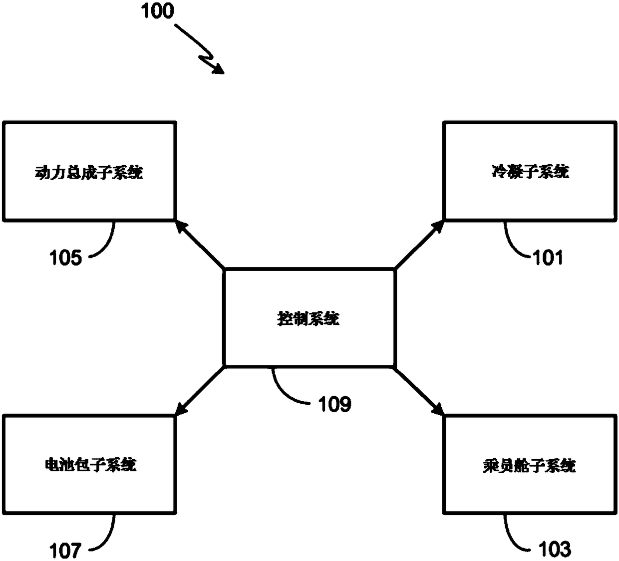
[0029] See attached figure 1 , 2 A thermal management system 100 for a new energy vehicle, especially a pure electric vehicle, includes a condensation subsystem 101 , a passenger compartment subsystem 103 , a powertrain subsystem 105 , and a battery pack subsystem 107 . The thermal management system 100 also requires a control system 109 . One or more of the other subsystems of the condensation subsystem 101 are thermally coupled together for the purpose of reducing the temperature of other thermal systems.

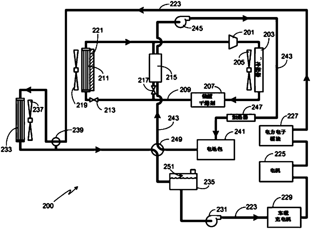
[0030] See attached figure 2 , the condensing subsystem 101 includes a compressor 201, which can compress the low-temperature refrigerating vapor in the condensing subsystem into high-temperature refrigerating vapor. When the v...


PUM


Abstract

The invention relates to the technical field of automobile battery system control, and discloses a single cooling water tank new energy vehicle thermal management system. The single cooling water tanknew energy vehicle thermal management system comprises a condensation subsystem, a power assembly subsystem and a battery pack subsystem, and is controlled by a control system. The condensation subsystem comprises a cooling circuit composed of a compressor, a condenser and an evaporator, and the power assembly subsystem comprises a power circuit formed by a motor, a cooling water tank, a first water pump and a pipeline. The battery pack subsystem includes a battery pack circuit formed by a battery pack, a second water pump and a pipeline. A control valve is installed between a pipeline through which the power circuit is connected to the inlet position of the water tank and a pipeline at the outlet position of the battery pack, and the control system includes a plurality of sensors and a control module which are disposed in the system. The single cooling water tank new energy vehicle thermal management system enables new energy vehicles to switch in two cooling circuit modes to adapt to different working conditions of the vehicles.

Description

technical field [0001] The invention relates to the technical field of automobile battery system control, in particular to a heat management system for new energy automobiles with a single cooling water tank. Background technique [0002] The vast majority of automotive work around the world today is done by burning gasoline in internal combustion engines. Using these vehicles is dependent on fossil fuels, which creates two problems. First, the amount of this fuel is limited, and availability varies from region to region, with some being limited. A general upward trend in gasoline prices is common. Both scenarios could have huge implications at the consumer level. Second, fossil fuel combustion is one of the main sources of carbon dioxide, a greenhouse gas and thus one of the main contributors to global warming. Therefore, it is necessary to find a new power system to replace the current internal combustion engine. [0003] Pure electric vehicles are undoubtedly one of ...

Claims


Application Information

Patent Timeline
Patent Type & Authority Applications(China)
IPC IPC(8): B60H1/00B60H1/22B60K1/00B60L11/18
CPCB60H1/00392B60H1/00485B60H1/2215B60H2001/2281B60H2001/2293B60K1/00B60K2001/006B60L58/26B60L58/27Y02T10/70
Inventor 任奕王英刘文鹏
Owner 上海牛仁汽车有限公司
Why Eureka
Try Eureka