Centrifugal tube

A technology of centrifuge tubes and tube bodies, which is applied in the field of cell separation, can solve problems such as difficulty in ensuring the purity of mononuclear cells, and achieve the effect of simple and convenient operation

Active Publication Date: 2018-09-28
苏州呼呼健康科技有限公司
View PDF3 Cites 1 Cited by
  • Summary
  • Abstract
  • Description
  • Claims
  • Application Information

AI Technical Summary

Problems solved by technology

[0004] The purpose of the present invention is to provide a centrifuge tube to improve the problem that the existing centrifuge tube is difficult to ensure the purity of the isolated mononuclear cells

Method used


Image

  • Centrifugal tube
  • Centrifugal tube
  • Centrifugal tube

Examples


Embodiment 1

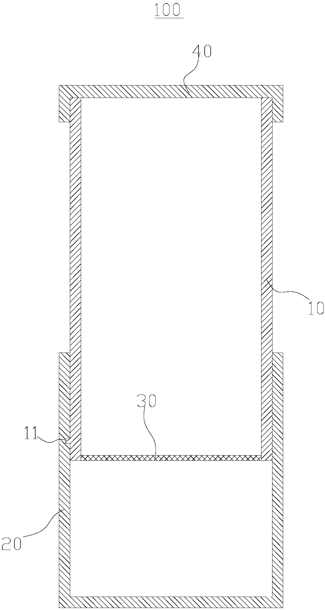
[0042] like figure 1 As shown, this embodiment provides a centrifuge tube 100, including an upper tube body 10, a lower tube body 20, a filter membrane 30 and a cap 40, and the bottom end of the upper tube body 10 is detachably inserted into the lower tube body 20 , the filter membrane 30 is arranged at the bottom of the upper tube body 10 , and the tube cover 40 is covered on the top of the upper tube body 10 .

[0043] Wherein, the upper pipe body 10 is cylindrical, which is a hollow structure with openings at both ends of the top and bottom. In this embodiment, a protruding portion 11 is provided on the outer wall of the upper tube body 10, the protruding portion 11 is cylindrical, the axis direction of the protruding portion 11 is consistent with the radial direction of the upper tube body 10, and the protruding portion 11 is close to at the bottom of the upper body 10.

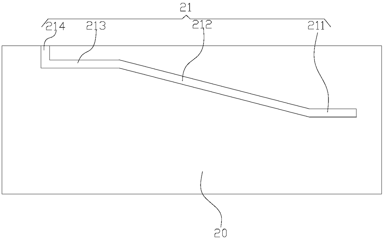
[0044] The lower tube body 20 is cylindrical, and the lower tube body 20 has an open top structure, ...

Embodiment 2

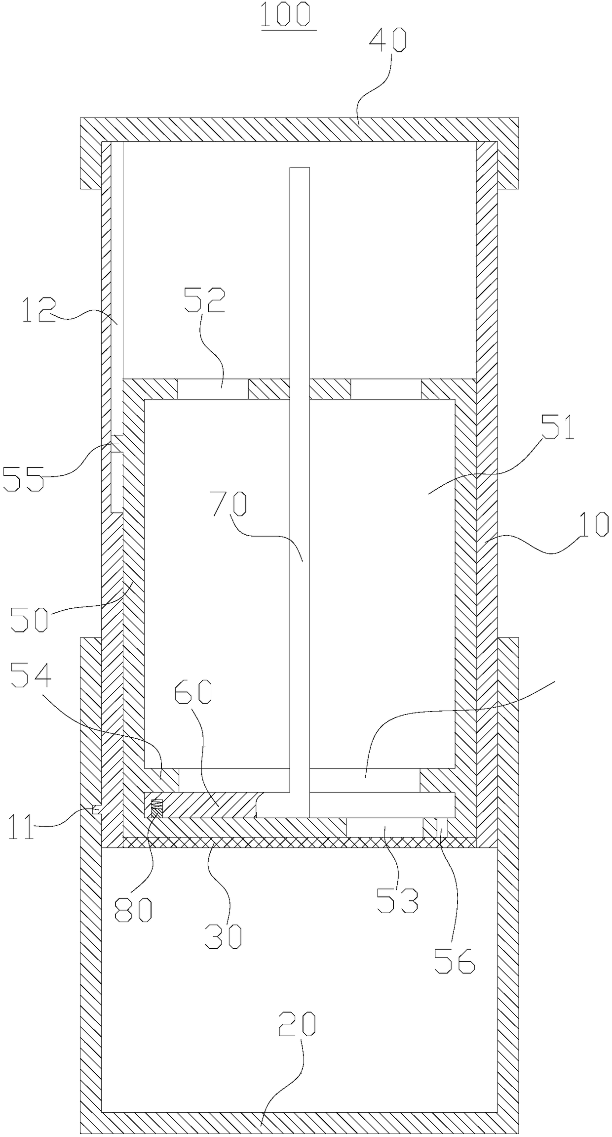
[0051] like image 3 As shown, this embodiment provides a centrifuge tube 100 , which differs from the above embodiments in that it further includes an inner tube body 50 , a sealing member 60 and a rotating shaft 70 .

[0052] Wherein, the inner tube body 50 is cylindrical, and the outer diameter of the inner tube body 50 matches the inner diameter of the upper tube body 10 . A cylindrical accommodation space 51 is formed inside the inner tube body 50. The inner tube body 50 has a top wall and a bottom wall. The top wall of the inner tube body 50 is provided with a liquid inlet 52. The liquid port 53 , the liquid inlet port 52 and the liquid outlet port 53 are all in communication with the receiving holes. In this embodiment, there are multiple liquid inlets 52 and one liquid outlet 53 , and the liquid outlet 53 is not set at the center of the bottom wall of the inner tube body 50 .

[0053] In addition, in this embodiment, a ring protrusion 54 is provided on the inner side...


PUM


Abstract

The invention provides a centrifugal tube, and belongs to the technical field of cell separation. The centrifugal tube comprises an upper tube body, a lower tube body, a filtering membrane and a tubecap, wherein the upper tube body is of a structure with openings at the top end and the bottom end, the upper tube body is of a structure with an opening at the top end, the bottom end of the upper tube body is detachably inserted into the lower tube body, and the outer side wall of the upper tube body is in seal fit with the inner side wall of the lower tube body. The filtering membrane is plugged at the bottom end of the upper tube body and can allow separation liquid to pass and stop mononuclear cells from passing. The tube cap covers the top end of the upper tube body. As the filtering membrane can allow the separation liquid to pass and stop the mononuclear cells from passing, the separation liquid and red cells are positioned on the lower portion of the filtering membrane, an albuginea layer with blood plasma and the mononuclear cells are positioned on the filtering membrane and effectively isolated from the separation liquid and the red cells, and the purity of the separated mononuclear cells is ensured.

Description

technical field [0001] The invention relates to the technical field of cell separation, in particular to a centrifuge tube. Background technique [0002] Currently, peripheral blood mononuclear cells (PBMC cells) include lymphocytes and monocytes. To detect lymphocytes in vitro, the first step is to separate peripheral blood mononuclear cells. At present, the main separation method is density gradient centrifugation, because the specific gravity of each component in blood is different, so it can be separated. The density of red blood cells is higher than that of the separation liquid, and they are deposited at the bottom of the tube; the platelets are suspended in the plasma due to their low density, and only mononuclear cells with a density comparable to that of the separation liquid are densely packed in the interface between the plasma layer and the separation liquid, showing a white film shape, that is, Buffy coat, mononuclear cells can be obtained by aspirating the buf...

Claims


Application Information

Patent Timeline
Patent Type & Authority Applications(China)
IPC IPC(8): C12M1/24C12M1/12
CPCC12M23/08C12M29/04C12M47/04
Inventor 李丹江南
Owner 苏州呼呼健康科技有限公司
Why Eureka
Try Eureka