Gas compressor with high-pressure ratio for fuel cell system and energy recycling turbine device

A fuel cell system and energy recovery technology, which is applied in the direction of fuel cells, pump devices, electrical components, etc., can solve the problems of undisclosed, uneconomical technical solutions, and occupying installation space, etc., and achieves simple structure, reduced installation space, and convenient installation and the effect of debugging

Active Publication Date: 2018-09-28
NAVAL UNIV OF ENG PLA
View PDF5 Cites 1 Cited by
  • Summary
  • Abstract
  • Description
  • Claims
  • Application Information

AI Technical Summary

Problems solved by technology

Although this invention provides a structure and method for recovering the high-pressure gas energy discharged from the fuel cell exhaust system by using a turbine structure, firstly, the idea of ​​the invention is to recover the high-pressure gas energy discharged from the fuel cell exhaust system through a generator Power generation, which does not disclose the technical problem to be solved by the present invention—that is, how to reduce the energy consumption of the electric motor used to drive the compressor; secondly, this invention is equivalent to adding a new set of Energy recovery system, the new energy recovery system will inevitably occupy the installation space of the original equipment, resulting in the need to redesign the structure of the original equipment, so this technical solution is uneconomical

Method used


Image

  • Gas compressor with high-pressure ratio for fuel cell system and energy recycling turbine device
  • Gas compressor with high-pressure ratio for fuel cell system and energy recycling turbine device
  • Gas compressor with high-pressure ratio for fuel cell system and energy recycling turbine device

Examples


Embodiment Construction

[0021] In order to make the object, technical solution and advantages of the present invention more clear, the present invention will be further described in detail below in conjunction with the accompanying drawings and embodiments. It should be understood that the specific embodiments described here are only used to explain the present invention, not to limit the present invention.

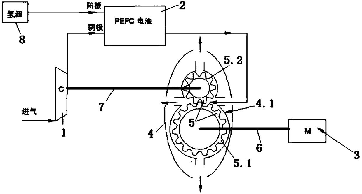
[0022] It can be known from a fuel cell system high pressure ratio compressor and energy recovery turbine device shown in the accompanying drawings that the present invention includes a compressor 1, a fuel cell 2, an electric motor 3, an energy recovery turbine 4 and a hydrogen source 8; The input end is connected to the atmosphere, the anode input end of the fuel cell 2 is connected to the hydrogen source 8 through a pipeline, the cathode input end of the fuel cell 2 is connected to the compressor 1 through a pipeline, and the cathode output end of the fuel cell 2 is connected to the energy rec...


PUM


Abstract

The invention discloses a gas compressor with a high-pressure ratio for a fuel cell system and an energy recycling turbine device. The gas compressor comprises a gas compressor body, a fuel cell, an electromotor, an energy recycling turbine and a hydrogen source, wherein an input end of the gas compressor body communicates with the atmosphere; an anode input end of the fuel cell is connected withthe hydrogen source through a pipeline; a cathode input end of the fuel cell is connected with the gas compressor body through a pipeline; a cathode output end of the fuel cell is connected with the energy recycling turbine through a pipeline; a transmission gear group is arranged in the energy recycling turbine; a driving gear of the transmission gear group is connected with an output end of theelectromotor through a first shaft; and a driven gear of the transmission gear group is connected with gas compressor impellers of the gas compressor body through a second shaft. According to the gascompressor with the high-pressure ratio for the fuel cell system and the energy recycling turbine device disclosed by the invention, the electromotor and the turbine are arranged aside the gas compressor, and energy discharged from an air exhaust system of the fuel cell is recycled by utilizing the turbine so as to drive the gas compressor, and therefore, power, consumed by driving the gas compressor, of the electromotor is effectively reduced, and the comprehensive efficiency of the fuel cell is effectively improved.

Description

technical field [0001] The invention relates to a fuel cell energy recovery turbine device, belonging to the technical field of fuel cells, in particular to a fuel cell system high pressure ratio compressor and an energy recovery turbine device. Background technique [0002] At present, the compressor that provides air in the high-pressure gas supply system of the fuel cell consumes a lot of energy. The power consumption of the compressor affects the comprehensive power generation efficiency of the fuel cell. If the turbine device is considered to recover part of the energy, the turbine device can be fully utilized to recover Most of the energy consumed by the compressor. [0003] In the description of the Chinese invention patent CN201710244569, an energy recovery structure for the exhaust system of a fuel cell vehicle is disclosed, which adds a turbine-driven generator to the exhaust passage of the fuel cell vehicle. The turbine-driven generator includes a turbocharger, a ...

Claims


Application Information

Patent Timeline
Patent Type & Authority Applications(China)
IPC IPC(8): F01C1/18F01C13/04F04D25/04F04D25/08H01M8/04111
CPCF01C1/18F01C13/04F04D25/024F04D25/04F04D25/08H01M8/04111Y02E60/50
Inventor 梁前超李龙徐百汇严小平赵建锋黄潜龙任济民方昆罗菁
Owner NAVAL UNIV OF ENG PLA
Why Eureka
Try Eureka