Detonator short-interval detonation blasting method for reducing ground blasting vibration

A blasting vibration and detonator technology, applied in the field of blasting, can solve problems such as reducing blasting vibration, achieve the effect of improving shovel loading efficiency, good crushing effect, and guaranteed effect

Inactive Publication Date: 2018-09-28
厦门爆破工程有限公司 +1
View PDF6 Cites 4 Cited by
  • Summary
  • Abstract
  • Description
  • Claims
  • Application Information

AI Technical Summary

Problems solved by technology

However, during the blasting construction process in the tunnel, there will be hazards such as noise, flying stones, poisonous gas, dust and seismic waves. It evolves into a compressive stress wave that propagates along the rock-soil medium to the lining of nearby buildings, and the compressive stress wave will undergo complex diffraction, transmission and reflection phenomena at the lining of the building. At this time, if it is a building that is sensitive to vibration Due to the possibility of damage due to the action of compressive stress, shear stress and tensile stress, the seismic waves generated by blasting vibration will inevitably have adverse effects on surrounding buildings or facilities. How to overcome the impact of underground blasting on ground buildings as much as possible Impact becomes a technical problem
[0003] The application number is 201410710171.3 Chinese patent "tunnel smooth blasting method" discloses a tunnel smooth blasting method, including cutting, blasting, etc., in the case of meeting the half eye rate and footage, reducing the bottom plate holes, reducing costs and improving efficiency , but this blasting method does not involve a solution to reduce blasting vibration

Method used


Image

  • Detonator short-interval detonation blasting method for reducing ground blasting vibration
  • Detonator short-interval detonation blasting method for reducing ground blasting vibration
  • Detonator short-interval detonation blasting method for reducing ground blasting vibration

Examples


Embodiment Construction

[0028] Delayed blasting technology for vibration reduction is widely used in underground engineering. The delayed initiation method can greatly reduce the total amount of charge for a single initiation, thereby reducing blasting vibration. At the same time, due to the time interval, the seismic wave in the rock and soil forms a phase difference, which avoids the superposition of the peak value of the seismic wave. When the phase is reversed properly, the peak and trough of the seismic wave are superimposed, and the particle vibration velocity will be greatly reduced.

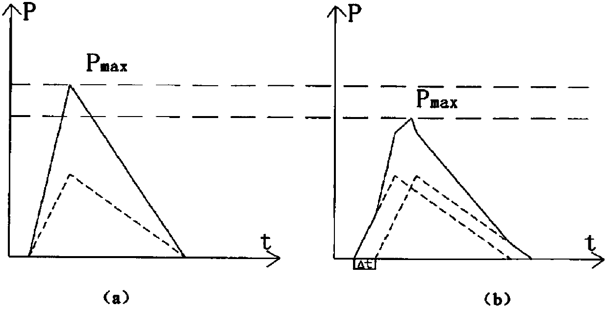
[0029] like figure 1 As shown, in the simplified schematic diagram of seismic waves, the dotted line in the figure is the action time course produced by a single explosive source explosion, and the solid line is the action time course produced by the superposition of two explosive sources. like figure 1 As shown in (a): when detonated at the same time, the peak value is equal to twice the peak value of the vibr...


PUM


Abstract

The invention discloses a detonator short-interval detonation blasting method for reducing ground blasting vibration. The blasting area is divided into two symmetric areas on the left and the right with the center line of a tunnel face of a blasting tunnel as the boundary. The two sides of the center line are provided with a plurality of symmetric underholing holes, auxiliary holes and peripheralholes, wherein the underholing holes are formed in the center area of the tunnel face, the peripheral holes are formed in the periphery of the tunnel face, the auxiliary holes are formed between the underholing holes and the peripheral holes, and during implementation, in the same row, hole-by-hole symmetric delayed detonation is conducted. According to the detonator short-interval detonation blasting method, electronic detonator hole-by-hole sequential detonation is adopted, for different types of cannon holes, vibration waves transmitted to the ground interfere with one another and are partially offset through setting of the optimal delay time of electronic detonators, the blasting effect of the construction smooth surface can be guaranteed, the defect that traditional smooth surface blasting vibration is large can be overcome, and influences on ground buildings are finally reduced.

Description

technical field [0001] The invention belongs to the technical field of blasting, and in particular relates to a tunnel blasting method capable of reducing ground blasting vibration, in particular to a blasting method based on digital electronic detonator short-interval symmetrical detonation. Background technique [0002] In the construction of tunnels and other underground operations in cities, due to the complex and changeable geological conditions, it is inevitable to encounter various rock conditions. If complete and hard rock conditions are encountered during tunnel excavation, due to the low efficiency and high cost of mechanical excavation, the drill and blast method with outstanding advantages such as high construction efficiency and fast construction progress is often used for construction. However, during the blasting construction process in the tunnel, there will be hazards such as noise, flying stones, poisonous gas, dust and seismic waves. It evolves into a com...

Claims


Application Information

Patent Timeline
Patent Type & Authority Applications(China)
IPC IPC(8): F42D3/04F42D1/00F42D1/08
Inventor 杨朝阳许黎明林中原张大成李少波杨育肖绍清林树枝刘典基刘文辉林友辉沈顺平
Owner 厦门爆破工程有限公司
Why Eureka
Try Eureka