
Display panel, display panel preparation method and display device

A display panel and display area technology, applied in manufacturing tools, welding equipment, laser welding equipment, etc., can solve problems such as failure of the glass glue layer, easy to leave cracks, and failure of the packaging process, so as to reduce the contact area of ​​the end surface and realize narrow Frame design to ensure the effect of encapsulation

Active Publication Date: 2018-09-28
KUNSHAN GO VISIONOX OPTO ELECTRONICS CO LTD
View PDF7 Cites 8 Cited by
  • Summary
  • Abstract
  • Description
  • Claims
  • Application Information

AI Technical Summary

Problems solved by technology

However, when the existing display panel is cutting the glass glue layer, cracks are likely to be left on the cutting end surface of the glass glue layer, and the expansion of micro-cracks is likely to induce the failure of the glass glue layer, thereby causing the failure of the entire packaging process.
Existing display panels and packaging methods not only have relatively poor packaging effects but also relatively low packaging yields and relatively low production processes in the entire assembly line when designing narrow bezels and processes that require compressed cutting margins.

Method used


Image

  • Display panel, display panel preparation method and display device
  • Display panel, display panel preparation method and display device
  • Display panel, display panel preparation method and display device

Examples


Embodiment Construction

[0027] The technical solutions in the method embodiments will be clearly and completely described below in conjunction with the accompanying drawings in the method embodiments. Obviously, the described embodiments are only part of the embodiments of the method, not all of them. Based on the embodiments in this method, all other embodiments obtained by persons of ordinary skill in the art without making creative efforts belong to the scope of protection of this method.

[0028] It should be noted that when a component is said to be "mounted on" another component, it may be directly mounted on another component or there may be an intervening component. When a component is said to be "set on" another component, it may be set directly on the other component or there may be an intervening component at the same time. When a component is said to be "fixed" to another component, it may be directly fixed to the other component or there may be an intervening component at the same time. ...


PUM


Abstract

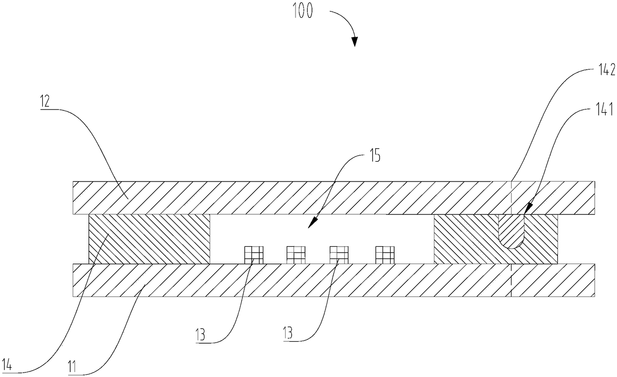
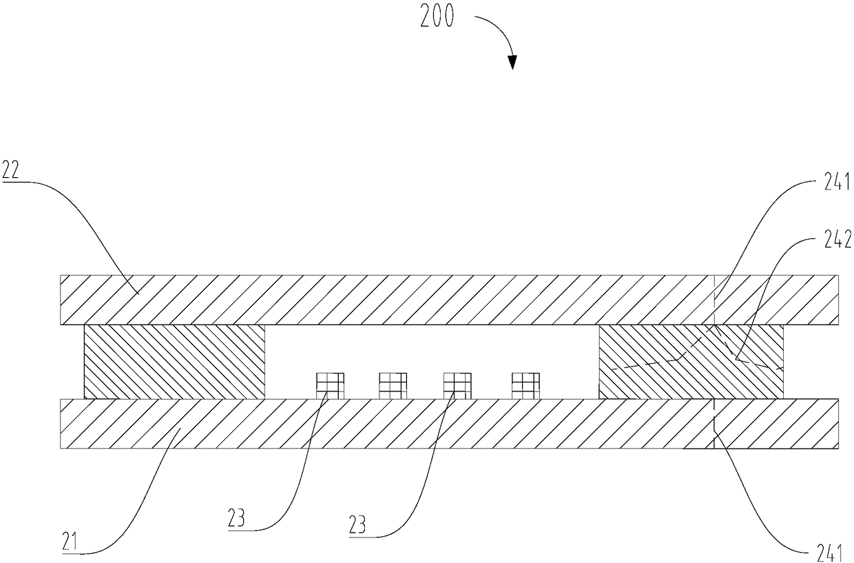
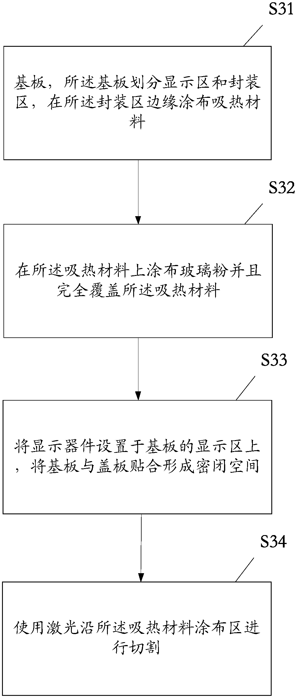
The invention provides a display panel, comprising a base plate, a cover plate set opposite to the base plate, and a packaging layer which is adhered with the base plate and the cover plate. A sealedspace for placing display devices is encircled by the base plate, the packaging layer and the cover plate. A groove is set on the packaging layer. The opening of the groove faces or back on to the cover plate. The groove is filled with a solid heat-absorption material. The invention also provides a packaging method and a display device. According to the display panel provided by the invention, through setting of the groove on the packaging layer, when a cutter cuts the packaging layer, the contact the side wall of the groove is avoided, so an end face contact area when the cutter processes thepackaging layer is reduced, and the cut margin is compressed. The narrow frame design is realized, and a packaging effect and a packaging yield are ensured.

Description

technical field [0001] The invention relates to the technical field of electronic display, in particular to a display panel, a packaging method and a display device. Background technique [0002] Display devices are screen display devices of electronic equipment such as mobile phones, tablets, and televisions, and are widely used in the field of electronic technology. Among many display devices, organic light-emitting display (Organic Light-Emitting Diode, OLED) has many advantages such as active light emission, high luminous brightness, high resolution, wide viewing angle, fast response speed, low energy consumption and flexibility. It has received widespread attention due to its characteristics, and it is very likely to replace liquid crystal display as the next generation of display technology. Many display devices, including OLED devices, contain organic layer materials that are extremely sensitive to water vapor and oxygen. It is necessary to package the display device...

Claims


Application Information

Patent Timeline
Patent Type & Authority Applications(China)
IPC IPC(8): H01L51/52B23K26/38
CPCB23K26/38H10K50/8426H10K50/87
Inventor 周萍薛慕蓉
Owner KUNSHAN GO VISIONOX OPTO ELECTRONICS CO LTD
Learn More