Permanent magnet synchronous heat pipe cooling electric spindle

A permanent magnet synchronous, electro-spindle technology, used in cooling/ventilation devices, electrical components, electromechanical devices, etc., can solve the problem of not meeting the needs of the heat dissipation of the motor-spindle shaft, not being able to dissipate the heat of the motor-spindle, and reducing the machining accuracy of high-speed machine tools and other problems, to achieve the effect of solving the problem of thermal deformation, high reliability and rapid cooling response

Inactive Publication Date: 2018-09-28
HARBIN UNIV OF SCI & TECH
View PDF3 Cites 3 Cited by
  • Summary
  • Abstract
  • Description
  • Claims
  • Application Information

AI Technical Summary

Problems solved by technology

The frictional heating of the high-speed electric spindle bearing and the heat loss of the built-in motor are unavoidable. The heat generation of the bearing is mainly caused by the friction heat between the rolling body of the bearing and the inner and outer rings of the bearing. The heat generated by the loss of the built-in motor is mainly caused by the copper loss of the stator winding and the iron loss of the rotor. And the heat generated by the rotor iron loss accounts for 1 / 3 of the heat loss of the motor, and if the heat generated by the high-speed electric spindle cannot be dissipated in time, the accumulated heat will change the relationship between the motor, bearings and related components. Thermodynamic properties, causing serious thermal deformation of the spindle, will lead to reduced machining accuracy of high-speed machine tools
[0003] In order to improve the heat dissipation of the electric spindle, the existing technology usually sets up a cooling channel on the inner wall of the spindle shell, and uses water circulation cooling to dissipate heat. Although this design can improve the overall heat dissipation performance of the electric spindle to a certain extent, it cannot meet the requirements for Heat dissipation requirements for fixed parts such as electric spindle shaft core, bearing assembly and motor stator
In addition, the trigger time of water circulation cooling is long, and the heat dissipation efficiency is also low, which cannot dissipate the heat generated inside the electric spindle in a timely manner.
Some people also proposed to use the heat pipe cooling method to cool the electric spindle core. Although this method can effectively reduce the temperature of the spindle core and the cooling trigger time is short, due to its structural defects, the heat pipe is installed on the spindle shaft. When the core is at the core, the heat pipe will deteriorate the vibration performance of the spindle when it rotates with the spindle at high speed, which cannot meet the requirements of machining accuracy. In addition, the heat pipe rotates with the spindle at high speed, and the large centrifugal force will seriously affect the heat dissipation efficiency of the heat pipe.

Method used


Image

  • Permanent magnet synchronous heat pipe cooling electric spindle

Examples


Embodiment Construction

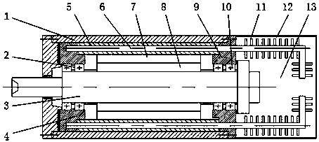
[0012] Below, in conjunction with accompanying drawing and specific embodiment, the present invention will be further described: figure 1 As shown, a permanent magnet synchronous heat pipe cooling electric spindle includes a spindle housing 1, a spindle 3 is installed in the spindle housing 1, the two ends of the spindle 3 are respectively supported by a front bearing 2 and a rear bearing 10, and the front bearing 2 and the rear bearing 10 are in turn They are respectively installed on the front bearing assembly 4 and the rear bearing assembly 9, and the front bearing assembly 4 and the rear bearing assembly 9 are fixed on the inner wall of the main shaft housing 1. In addition, a motor rotor 8 is set in the middle of the main shaft 3, and the main shaft 3 Interference connection, the heat pipe base 5 is fixed on the inner wall of the middle part of the main shaft housing 1, the motor stator 7 is installed on the inner ring of the heat pipe base 5, and the cooling chamber net c...


PUM


Abstract

The invention relates to a permanent magnet synchronous heat pipe cooling electric spindle, comprising a spindle housing, wherein a spindle is mounted in the spindle housing, the two ends of the spindle are respectively supported by a front bearing and a rear bearing, the front bearing and the rear bearing are respectively mounted on a front bearing assembly and a rear bearing assembly, and the heat generated by the front and rear bearings can be greatly transmitted; a heat pipe base is fixed in the middle of the spindle housing, a heat dissipation chamber is designed at the rear end of the spindle housing, and an inorganic heat pipe passes through the heat pipe base, with a condensation end inserted into the front bearing assembly and passing through the rear bearing assembly, and an evaporation end extending into the heat dissipation chamber to absorb the heat generated by the bearings and a motor stator to a certain extent; and at the same time, a heat sink is arranged at the evaporation end of the heat pipe. The electric spindle is improved relative to other spindle devices in internal structure, heat pipe mounting position, motor selection and cooling method; a permanent magnet synchronous motor is selected, so the rotor has low heat generation; and the overall structure is simple, the operation is stable, and the service life of the electric spindle can be prolonged.

Description

technical field [0001] The invention relates to the technical field of processing equipment, in particular to an electric spindle cooled by a permanent magnet synchronous heat pipe. Background technique [0002] Entering the 21st century, high-speed cutting technology has entered an unprecedented and rapid development period. The strong demand for high-speed and high-precision machining in the manufacturing industry has also promoted the development of electric spindles, and it has also brought some new technical problems to high-speed electric spindles. , and the heat dissipation of the electric spindle has become one of the hot issues of research. The frictional heating of the high-speed electric spindle bearing and the heat loss of the built-in motor are unavoidable. The heat generation of the bearing is mainly caused by the friction heat between the rolling body of the bearing and the inner and outer rings of the bearing. The heat generated by the loss of the built-in mo...

Claims


Application Information

Patent Timeline
Patent Type & Authority Applications(China)
IPC IPC(8): H02K9/20H02K5/20
CPCH02K9/20H02K5/20
Inventor 吴明阳孙宇杰程耀楠戴野李鹏飞
Owner HARBIN UNIV OF SCI & TECH
Why Eureka
Try Eureka