
System for cross-region signal transmission

A signal transmission, cross-ground technology, applied in the field of signal transmission, can solve the problems of weak anti-electromagnetic interference, difficult to make high pressure, large volume, etc., to achieve the effect of strong anti-electromagnetic interference and high utilization rate

Inactive Publication Date: 2018-09-28
UNIV OF ELECTRONIC SCI & TECH OF CHINA
View PDF5 Cites 1 Cited by
  • Summary
  • Abstract
  • Description
  • Claims
  • Application Information

AI Technical Summary

Problems solved by technology

Opto-coupling has the problems of greatly degraded performance and complex mechanism, which is prone to reliability problems as the use time becomes longer; differential electrical coupling transmits signals through differential lines, and the utilization efficiency of signal wires is low and power consumption is large. It is fatal to the transmission system; transformer coupling uses a transformer as a current coupling device, which has large volume, high power, and low transmission frequency, which is inconsistent with the goals of voltage, small volume, and high speed; capacitive coupling uses a high-voltage capacitor as a coupling device, and there is an anti- The problem of weak electromagnetic interference ability and difficulty in making high withstand voltage
[0004] In addition, there is also a digital isolation system solution based on an on-chip transformer in the prior art, which is based on a transformer implemented by a separate coupling coil integrated on an integrated circuit in the SiP package, and transmits the edge signal after the original signal modulation, and then in the secondary Level-to-edge signal recovery; but the above-mentioned digital isolation system solution cannot achieve better signal multiplexing due to its simple system, so it cannot break through the bandwidth limit of 100Mbps

Method used


Image

  • System for cross-region signal transmission
  • System for cross-region signal transmission
  • System for cross-region signal transmission

Examples


Embodiment

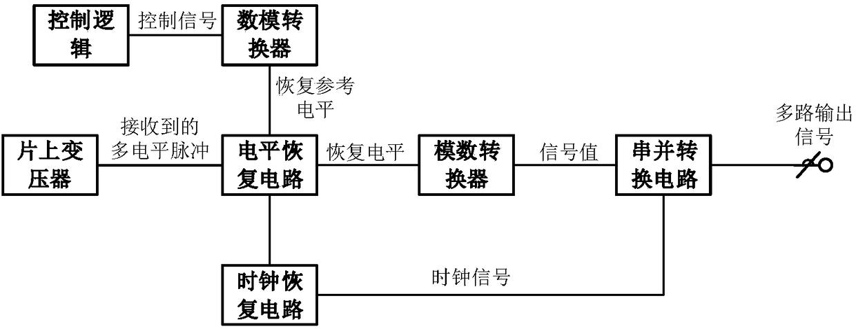
[0023] This embodiment provides a system for transmitting signals across the ground, which includes a group of circuit systems, and adjacent circuit systems are separated by an on-chip transformer group; the on-chip transformer group includes more than one on-chip transformer; adjacent circuit systems are separated by The on-chip transformers are communicatively connected; communications may include the exchange of control signals, timing signals, and / or data.

[0024] The set of circuit systems includes more than one pair of cooperating signal sending circuits and signal receiving short circuits; thus, the number of on-chip transformers in the digital isolation system can be greatly reduced, the transmission rate can be increased, and power consumption can be reduced.

[0025] The signal sending circuit includes a pulse generating circuit, a modulator and an oscillator; the oscillator is used to generate a clock signal; the clock signal and multiple data signals generate elect...


PUM


Abstract

The invention belongs to the technical field of signal transmission, and discloses a system for cross-region signal transmission. The system for cross-region signal transmission comprises a group of circuit systems, the neighboring circuit systems are separated through an on-chip transformer group; the on-chip transformer group comprises more than one on-chip transformer; the neighboring circuit systems are in communication connection through the on-chip transformer; one group of circuit systems comprises more than one pair of cooperatively used signal sending circuit and signal receiving short circuit; the signal sending circuit comprises a pulse generation circuit, a modulator and an oscillator; and a level signal is transmitted in the signal receiving circuit through the on-chip transformer group. According to the system provided by the invention, multiple levels are used for processing original multi-path data signals and the processed original multi-path data signals are transmitted through the on-chip transformer, thus, rate of data transmission is promoted exponentially while being matched with the on-chip transformers, and the promoted times of the rate of data transmissionare related to level digits. Meanwhile, anti-electromagnetic interference performance of the on-chip transformers is stronger than that of the conventional differential wiring, moreover, utilizationrate of the on-chip transformers is stronger than that of the conventional unmodulated digital isolator.

Description

technical field [0001] The invention belongs to the technical field of signal transmission, and in particular relates to a system for trans-territory signal transmission. Background technique [0002] Digital isolation system is an extremely important category in contemporary circuit systems, and is widely used in mines, telecommunications and other occasions that require long-distance communication, providing a relatively clean reference ground level for the transceiver end of the signal. In long-distance signal transmission, since the resistance value and parasitic inductance of the wire are proportional to the length of the wire, its ground level is very susceptible to space electromagnetic signals and current-resistance drop (IR Drop). When the circuit works in this environment , it is equivalent to adding a voltage jitter on the reference ground to the transmission signal, making the circuit unable to work normally. With the rapid development of the Internet of Things,...

Claims


Application Information

Patent Timeline
IPC IPC(8): H04B3/02H04B3/04H04B1/40
CPCH04B1/40H04B3/02H04B3/04
Inventor 曾敬源
Owner UNIV OF ELECTRONIC SCI & TECH OF CHINA
Learn More