

Material carrying mechanical arm capable of rotating and displacing and working method thereof
A technology for transporting machinery and rotating and shifting, which is applied in the field of robotic arms and can solve problems such as unsatisfactory use effects, low intelligence, and broken clips.
- Summary
- Abstract
- Description
- Claims
- Application Information
AI Technical Summary
Problems solved by technology
Method used
Image

Examples
Embodiment 1
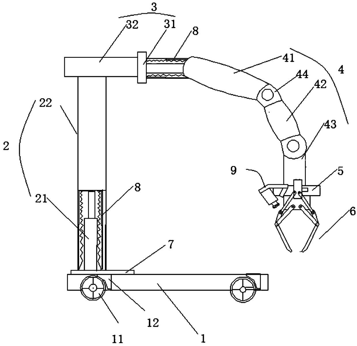
[0091] Such as figure 1 A rotating and shifting material handling mechanical arm is shown, including a base 1, a lifting column 2, a lateral movement mechanism 3, a mechanical arm 4, a connecting piece 5 and a mechanical claw 6 for retrieving, and the lifting column 2 is fixed by a rotating disk 7 On the base 1, the traversing mechanism 3 is arranged on the lifting column 2. The lifting column 2 includes a lifting cylinder 21 and a supporting column 22. The bottom of the lifting cylinder 21 is arranged on the rotating disk 7. The traversing mechanism 3 is a Horizontal cylinder 31 and crossbeam 32, described crossbeam 32 is connected with the piston rod of lift cylinder 21, and described horizontal cylinder 31 is arranged on crossbeam 32, and horizontal cylinder 31 piston rod is connected with mechanical arm 4, and material retrieving mechanical paw 6 passes connector 5 is connected to the mechanical arm 4, and the mechanical arm 4 and the mechanical claw 6 are controlled by in...
Embodiment 2
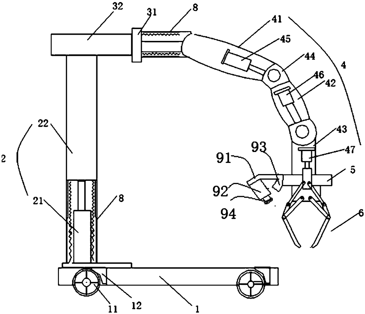
[0093] Such as figure 2 A rotating and shifting material handling mechanical arm is shown, including a base 1, a lifting column 2, a lateral movement mechanism 3, a mechanical arm 4, a connecting piece 5 and a mechanical claw 6 for retrieving, and the lifting column 2 is fixed by a rotating disk 7 On the base 1, the traversing mechanism 3 is arranged on the lifting column 2. The lifting column 2 includes a lifting cylinder 21 and a supporting column 22. The bottom of the lifting cylinder 21 is arranged on the rotating disk 7. The traversing mechanism 3 is a Horizontal cylinder 31 and crossbeam 32, described crossbeam 32 is connected with the piston rod of lift cylinder 21, and described horizontal cylinder 31 is arranged on crossbeam 32, and horizontal cylinder 31 piston rod is connected with mechanical arm 4, and material retrieving mechanical paw 6 passes connector 5 is connected to the mechanical arm 4, and the mechanical arm 4 and the mechanical claw 6 are controlled by i...
Embodiment 3
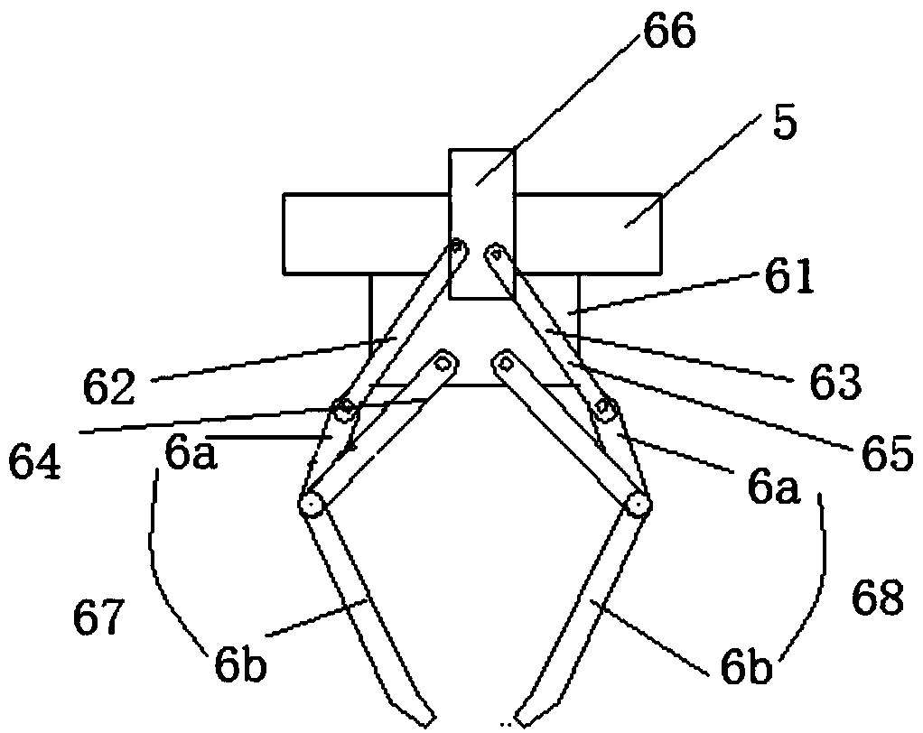
[0095] Such as figure 2 and 3 A rotating and shifting material handling mechanical arm is shown, including a base 1, a lifting column 2, a lateral movement mechanism 3, a mechanical arm 4, a connecting piece 5 and a mechanical claw 6 for retrieving, and the lifting column 2 is fixed by a rotating disk 7 On the base 1, the traversing mechanism 3 is arranged on the lifting column 2. The lifting column 2 includes a lifting cylinder 21 and a supporting column 22. The bottom of the lifting cylinder 21 is arranged on the rotating disk 7. The traversing mechanism 3 is a Horizontal cylinder 31 and crossbeam 32, described crossbeam 32 is connected with the piston rod of lift cylinder 21, and described horizontal cylinder 31 is arranged on crossbeam 32, and horizontal cylinder 31 piston rod is connected with mechanical arm 4, and material retrieving mechanical paw 6 passes connector 5 is connected to the mechanical arm 4, and the mechanical arm 4 and the mechanical claw 6 are controll...
PUM
 Abstract
Description
Claims
Application Information