Supercritical carbon dioxide Brayton cycle power component cooling, sealing and heat insulation system

A technology of Brayton cycle and power components, applied in the direction of electric components, engine components, cooling/ventilation devices, etc., can solve the safety impact of power components, increase the complexity of the system, and cannot effectively solve the heat conduction problems of turbine and motor shafts, etc. problem, to achieve the effect of high system security and simple structure

Pending Publication Date: 2018-10-09
XI AN JIAOTONG UNIV
View PDF6 Cites 12 Cited by
  • Summary
  • Abstract
  • Description
  • Claims
  • Application Information

AI Technical Summary

Problems solved by technology

This cooling scheme can effectively reduce the temperature in the motor chamber and ensure the safety of the power components, but it also increases the complexity of the system and cannot e

Method used


Image

  • Supercritical carbon dioxide Brayton cycle power component cooling, sealing and heat insulation system
  • Supercritical carbon dioxide Brayton cycle power component cooling, sealing and heat insulation system

Examples


Embodiment 1

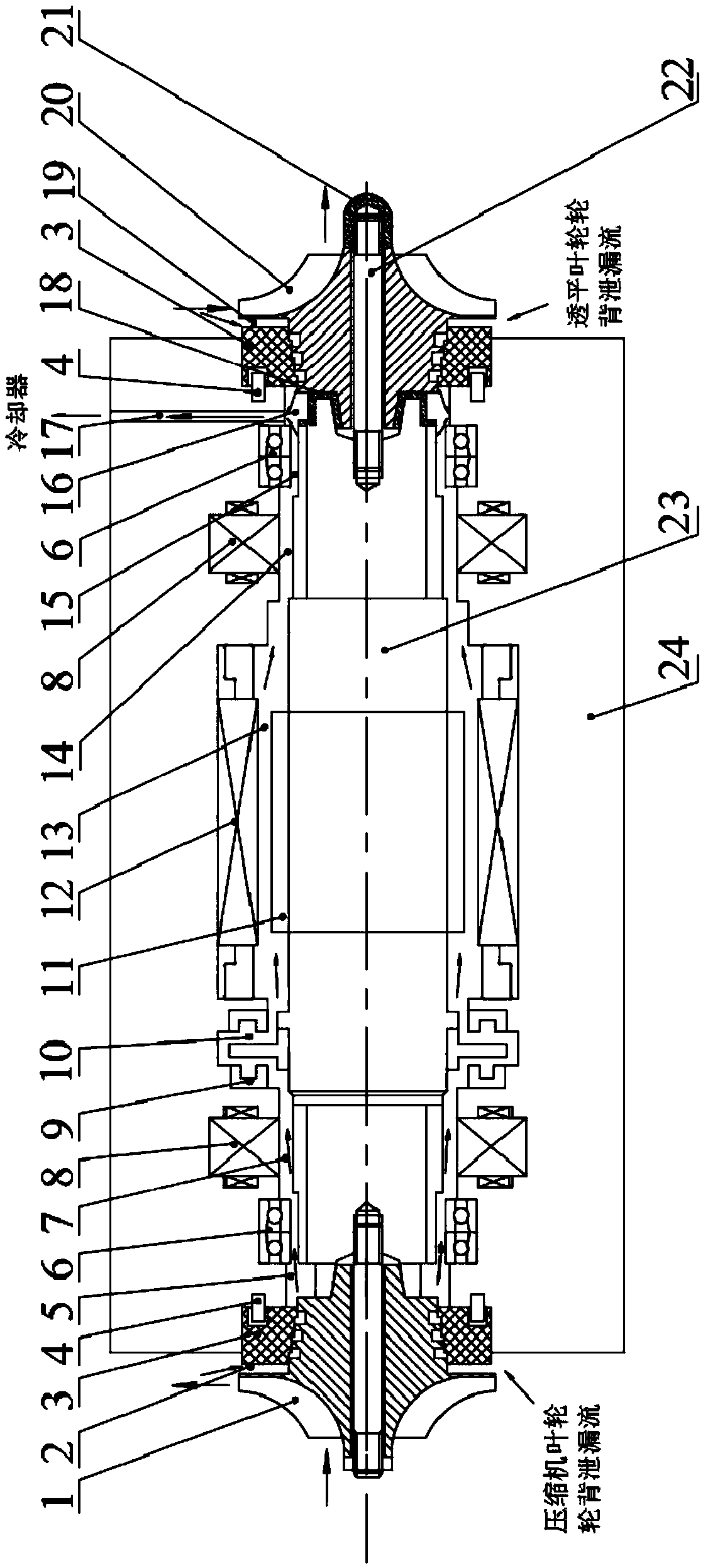
[0029] The invention provides a supercritical carbon dioxide Brayton cycle power component cooling sealing heat insulation system such as figure 1 As shown, the cooling, sealing and heat insulation system includes the back leakage gap 2 of the compressor impeller wheel, the wearable graphite labyrinth seal 3 arranged at both ends of the casing 24, a plurality of sequentially arranged and connected cooling passages, and a cold and hot working medium mixing chamber 16. Vent hole 17, heat insulation sleeve 18, leakage gap 19 at the back of turbine impeller wheel, connecting rod 22 and heat insulation diversion nut 21. The carbon dioxide circulating working fluid that enters the cooling channel through the back leakage gap 2 of the impeller of the compressor and the labyrinth seal is used as the cooling working fluid of the cooling sealing and heat insulation system.

[0030] Pins 4 are arranged on the casing 24, and the pins 4 are closely matched with the casing 24. The length of...

Embodiment 2

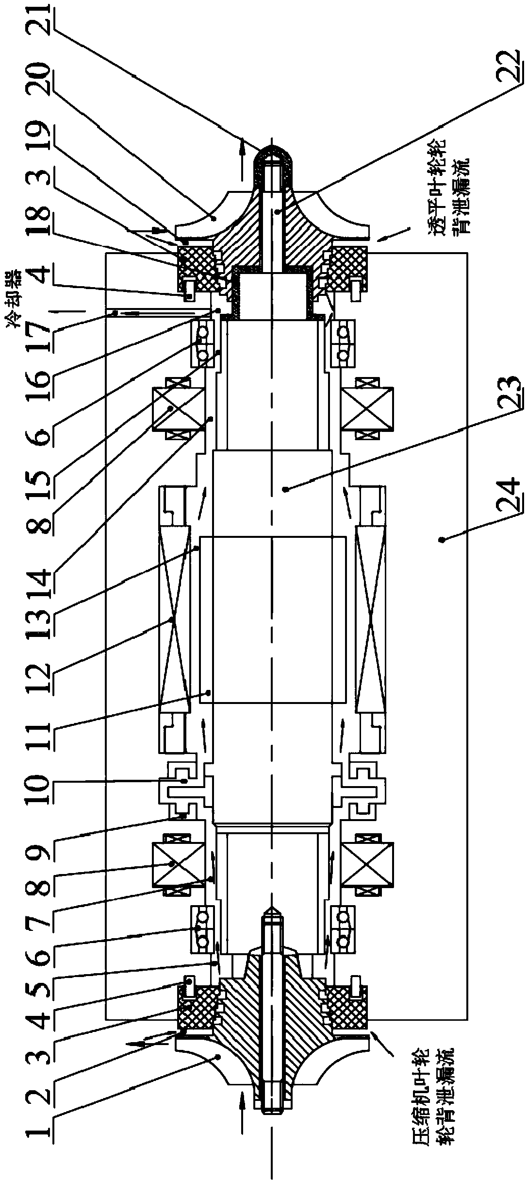
[0035] see figure 2 , the heat insulation sleeve 18 is located between the main shaft 23 and the turbine impeller 20, and is arranged on the end face of the main shaft 23 through an interference fit or threaded connection. The heat insulation sleeve 18 extends inward from the end of the main shaft 23 until the heat insulation The side of the sleeve 18 covers the side area of ​​the main shaft where the cold and hot working medium mixing chamber 16 is located. The heat insulating sleeve 18 completely separates the main shaft 23 from the high-pressure thermal fluid and the turbine impeller 20 to avoid direct contact with the main shaft 23 . The connecting rod 22 is fixed on the main shaft 23 , and the center line of the main shaft 23 coincides with the center line of the connecting rod 22 . The turbine impeller 20 is connected with the heat insulation sleeve 18 through an interference fit, the connecting rod 22 runs through the turbine impeller, the turbine impeller 20 does not...


PUM


Abstract

The invention provides a supercritical carbon dioxide Brayton cycle power component cooling, sealing and heat insulation system. The system comprises an annular gap between a machine shell and a mainshaft, wherein one end of the annular gap communicates with a compressor side leakage gap, a cold and hot working medium mixing chamber is arranged at the other end of the annular gap, the cold and hot working medium mixing chamber communicates with a turbine side leakage gap, and an exhaust hole communicating with the cold and hot working medium mixing chamber is formed in the machine shell. According to the supercritical carbon dioxide Brayton cycle power component cooling, sealing and heat insulation system, the annular gap is formed between the machine shell and the main shaft so that thelow-temperature leakage flow at the compressor side can be introduced into the machine shell so as to cool a motor, and is led out to a circulation system cooler through the exhaust hole after being mixed with the high-temperature leakage flow at the turbine side in the cold and hot working medium mixing chamber, then a high-temperature working medium can be prevented from damaging the main shaft,a bearing and a coil, and the structure is simple; and in addition, the main shaft is completely separated from the high-temperature working medium and a turbine through a heat-insulating sleeve, sothat the problem that the heat is transferred to the main shaft through the turbine is effectively solved.

Description

technical field [0001] The invention relates to a power component of a supercritical carbon dioxide Brayton cycle power generation system, in particular to a cooling, sealing and heat insulation system of the power component. Background technique [0002] The supercritical carbon dioxide Brayton cycle power generation system has many advantages such as high cycle efficiency, high energy density, compact structure, and low construction cost. It is considered to be one of the most promising energy conversion systems in both emerging and traditional energy fields. [0003] As one of the core components of the supercritical carbon dioxide Brayton cycle power generation system, power components mainly include compressors, turbines, motors, bearings and seals. For small power cycle systems, power components often use turbine-motor-compressor (T-A-C) layout plan, that is, the coaxial arrangement of the turbine, motor and compressor, the turbine and compressor are respectively insta...

Claims


Application Information

Patent Timeline
IPC IPC(8): F01K25/10F01D15/10F01D25/12F01D25/16F01D25/24H02K9/16
CPCH02K9/16F01D15/10F01D25/12F01D25/16F01D25/24F01K25/103
Inventor 邓清华蒋宇李军丰镇平
Owner XI AN JIAOTONG UNIV
Why Eureka
Try Eureka