Device and method for measuring gas micro-flow under experimental reservoir conditions

An experimental micro-flow technology, applied in the direction of measuring devices, suspension and porous material analysis, instruments, etc., can solve the problems that the flow is difficult to maintain stable and continuous, the error is large, and the accuracy of the sensor components is high.

Active Publication Date: 2018-10-09
CHINA PETROLEUM & CHEM CORP +1
View PDF2 Cites 4 Cited by
  • Summary
  • Abstract
  • Description
  • Claims
  • Application Information

AI Technical Summary

Problems solved by technology

[0002] The permeability of the core is an important parameter for reservoir evaluation, but the permeability of the tight core or shale core is very low, the gas flow rate in the core will be very slow, and the gas flow rate is difficult to accurately measure, which will give the physical parameters of the core Tests bring great difficulty
Moreover, most of the current core permeability tests are carried out at room temperature and the outlet is at atmospheric pressure, which cannot characterize the seepage characteristics of gas in the core under reservoir conditions. Therefore, it is necessary to accurately measure the flow rate of gas in tight cores under reservoir conditions.
[0003] Most of the indoor experiments use indirect methods to measure the gas flow rate under reservoir conditions. The current indoor experiment method is as follows: soap foam flow meter method, after the gas under the reservoir conditions passes through the back pressure valve, it passes through the metering soap foam at atmospheric pressure. The flow of gas is calculated by the time of the flow tube. First, the human error is large when using this flow measurement method. Second, when the gas passes through the back pressure valve, the flow is difficult to maintain stable and continuous, and the error is large; the throttling capillary method, this method is also the same. It converts the gas under the reservoir condition into atmospheric pressure for measurement, and cannot measure the flow rate of gas under pressure; the trace gas flow measurement device adopts float type gas flowmeter, which is not suitable for the flow measurement of gas under pressure; the gas flowmeter adopts The sensor component in the gas pipeline is used to measure the gas flow rate. When the flow rate is relatively small, the accuracy of the sensor component is required to be high. When the gas pressure is high, the sensor component may not be able to detect normally; the extremely small gas flow rate based on the vacuum standard of the static expansion method Measurement method, the gas in the calibration chamber is introduced into the vacuum system through a small hole, and the gas flow rate is obtained according to the conductance of the small hole and the pressure in the gas pressure decay system. This method is not suitable for the measurement of the gas flow rate under higher pressure in indoor experiments. Determination; for pressure gas flow measurement, a gas volume flow measurement device is proposed, which measures the pressure difference between the gas pressure and the initial pressure through a microprocessor, thereby generating a corresponding control signal to drive the syringe pump to pump at a corresponding speed, and measure Gas flow, when the flow rate is very small, the differential pressure signal detected by the microprocessor is relatively small, which requires high precision of the syringe pump; the high-pressure gas flow measurement standard device adopts the weighing method to measure the trace gas flow, in a section Within a short period of time, the change of gas quality is very small, and it is difficult to measure the quality difference before and after; The time difference of transit time in the gas may be difficult to distinguish, and it is difficult to detect the small flow of gas

Method used


Image

  • Device and method for measuring gas micro-flow under experimental reservoir conditions
  • Device and method for measuring gas micro-flow under experimental reservoir conditions

Examples


Embodiment

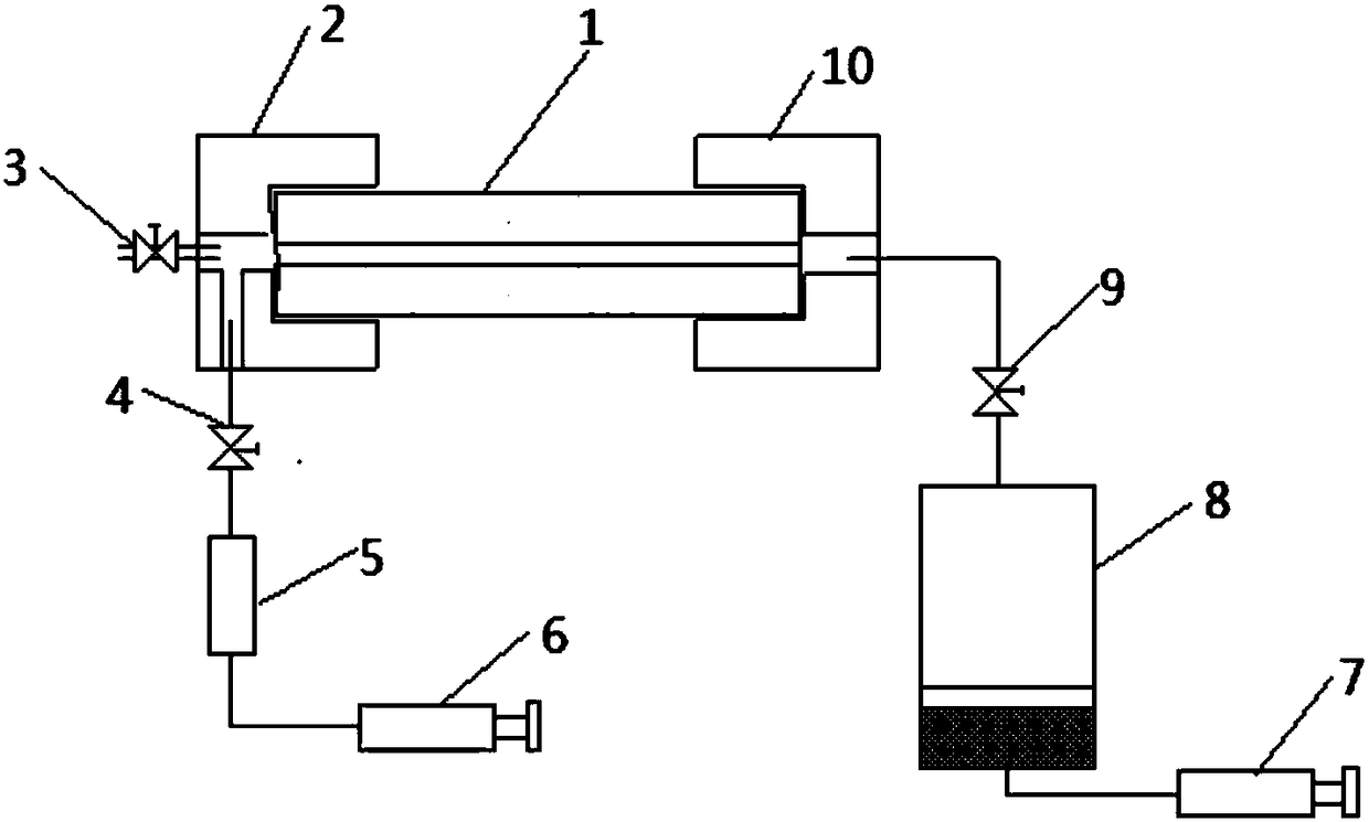
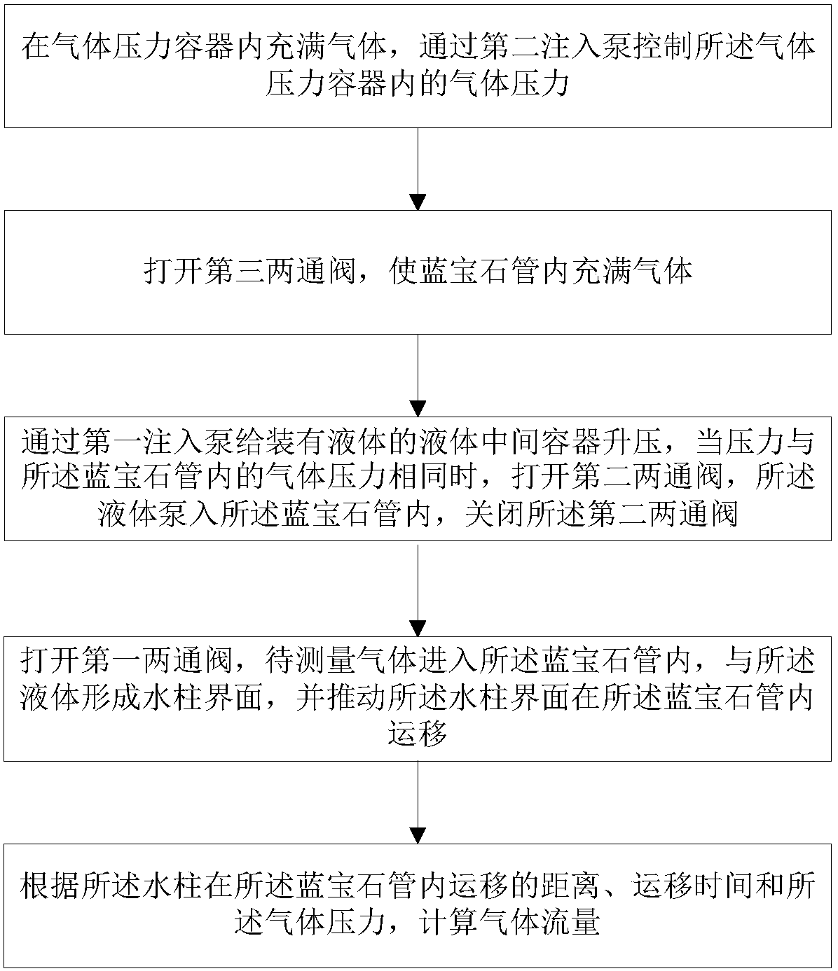
[0055] figure 1 A schematic diagram of an experimental gas micro-flow measurement device under reservoir conditions according to the present invention is shown. figure 2 A flow chart of a gas micro-flow measurement method under reservoir conditions for experiments according to the present invention is shown.

[0056] An experimental gas micro-flow measuring device under reservoir conditions of the present invention comprises:

[0057] sapphire tube 1;

[0058] The inlet joint 2 is connected to one end of the sapphire tube 1, and the inlet joint 2 includes an inlet air inlet and an inlet liquid inlet;

[0059] The outlet joint 10 is connected to the other end of the sapphire tube 1, and the outlet joint 10 includes an outlet air inlet;

[0060] The first injection pump 6, the first injection pump 6 is arranged at the inlet end;

[0061] A liquid intermediate container 5, the liquid intermediate container 5 is arranged between the first injection pump 6 and the liquid inlet...


PUM


Abstract

The invention discloses a device and a method for measuring gas micro-flow under experimental reservoir conditions. The device comprises: a sapphire tube, an inlet end joint which is connected to oneend of the sapphire tube and comprises a gas inlet of an inlet end and a liquid inlet of the inlet end, an outlet end joint which is connected to the other end of the sapphire tube and comprises the gas inlet of an outlet end, a first injection pump which is arranged at the inlet end, a liquid intermediate container which is arranged between the first injection pump and the liquid inlet of the inlet end, a second injection pump which is arranged at the outlet end, and a gas pressure container which is arranged between the second injection pump and the gas inlet of the outlet end. The device has advantages of being simple and convenient in operation method and relatively high in test result precision.

Description

technical field [0001] The invention relates to the technical field of oil and gas field development experiments, and more specifically, relates to a gas micro-flow measurement device and method under reservoir conditions for experiments. Background technique [0002] The permeability of the core is an important parameter for reservoir evaluation, but the permeability of the tight core or shale core is very low, the gas flow rate in the core will be very slow, and the gas flow rate is difficult to accurately measure, which will give the physical parameters of the core Testing poses great difficulties. Moreover, most of the current core permeability tests are carried out at room temperature and the outlet is at atmospheric pressure, which cannot characterize the seepage characteristics of gas in the core under reservoir conditions. Therefore, it is necessary to accurately measure the flow rate of gas in tight cores under reservoir conditions. . [0003] Most of the indoor e...

Claims


Application Information

Patent Timeline
Patent Type & Authority Applications(China)
IPC IPC(8): G01N15/08
CPCG01N15/0826
Inventor 赵清民潘伟义吕成远伦增珉王海涛赵春鹏郎东江周霞
Owner CHINA PETROLEUM & CHEM CORP
Why Eureka
Try Eureka