
Laser radar

A laser radar and laser pulse technology, applied in radio wave measurement systems, instruments, etc., can solve the problems of increasing the complexity of laser radar, limited detection distance of non-metallic objects, and low angular resolution

Active Publication Date: 2018-10-09
BEIJING JINGWEI HIRAIN TECH CO INC
View PDF14 Cites 16 Cited by
  • Summary
  • Abstract
  • Description
  • Claims
  • Application Information

AI Technical Summary

Problems solved by technology

Among them, the camera has the advantage of realizing high-resolution images, but it is a passive sensor, which is very sensitive to changes in ambient light, and the accuracy of object recognition is highly dependent on the algorithm; millimeter-wave radar has the advantage of working around the clock, namely It can still work normally in bad weather with rain, snow, haze and dust, but its angular resolution is low, the detection distance of non-metallic objects is limited, and pedestrians cannot be accurately perceived; lidar usually uses narrow pulse nanoseconds in the infrared band Class laser is used as the light source, using the time of flight to determine the distance of the object, and the centimeter-level point cloud information of the environment can be obtained by scanning the scanning module, which can accurately model the environment around the vehicle
[0004] However, although the existing coaxial mechanical rotary laser radar can achieve a 360° field of view in the horizontal direction and have a high horizontal angular resolution, because it uses multiple pairs of laser transceiver modules, each pair of laser transceiver The modules need to be adjusted and aligned separately, which makes the installation and adjustment difficult
Moreover, in order to realize 360° scanning, the laser transceiver module rotates with the motor, and the power supply module needs a slip ring or wireless power supply and wireless signal transmission to realize the power supply function and signal transmission, which limits the service life on the one hand and increases the the complexity of lidar

Method used


Image

  • Laser radar
  • Laser radar
  • Laser radar

Examples


Embodiment Construction

[0041] The following will clearly and completely describe the technical solutions in the embodiments of the present invention with reference to the accompanying drawings in the embodiments of the present invention. Obviously, the described embodiments are only some, not all, embodiments of the present invention. Based on the embodiments of the present invention, all other embodiments obtained by persons of ordinary skill in the art without making creative efforts belong to the protection scope of the present invention.

[0042] In order to make the above objects, features and advantages of the present invention more comprehensible, the present invention will be further described in detail below in conjunction with the accompanying drawings and specific embodiments.

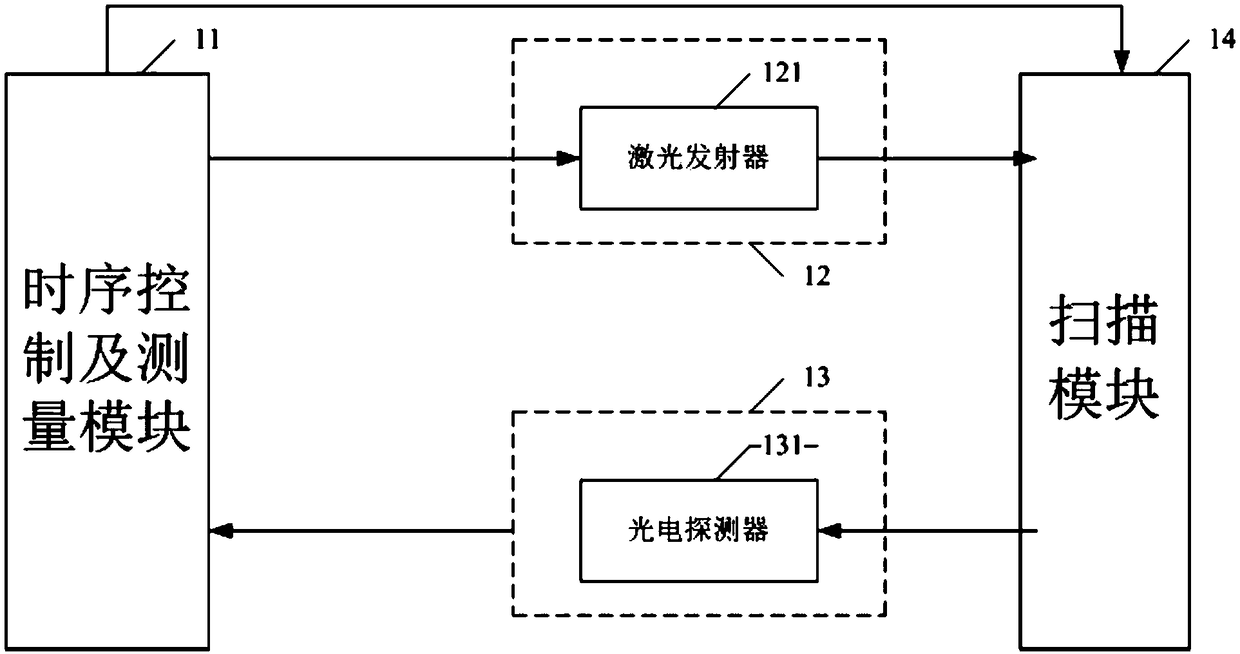
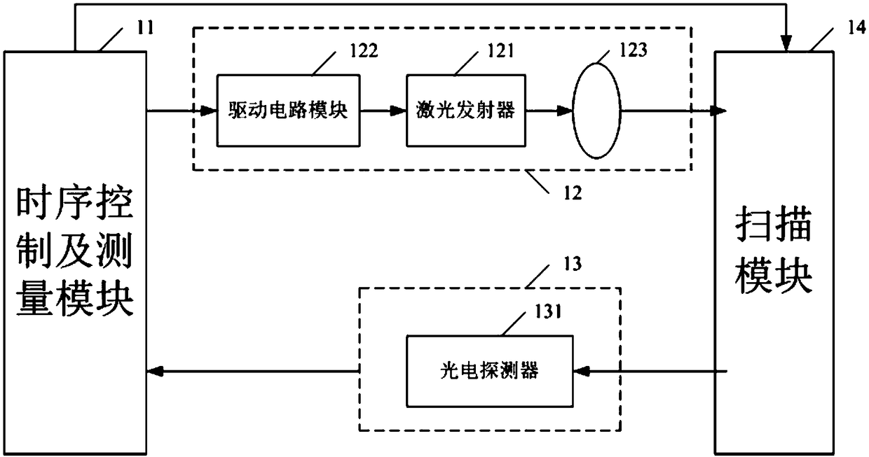
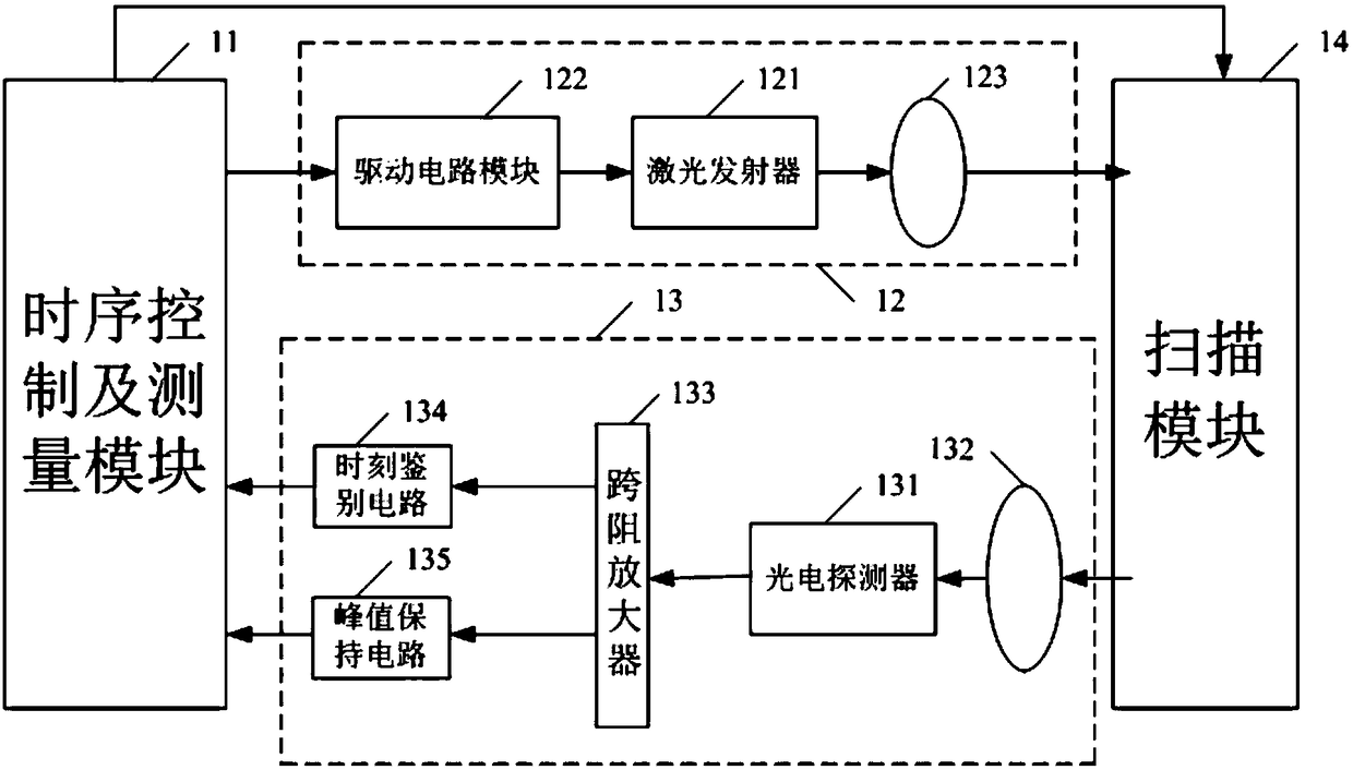
[0043] refer to figure 1 , figure 1 It is a schematic structural diagram of a laser radar provided by an embodiment of the present invention.

[0044] The laser radar includes: a timing control and measurement m...


PUM


Abstract

The invention discloses laser radar. The laser radar adopts a multi-channel laser transmitter and a multi-channel photoelectric detector, the positions of the multi-channel laser transmitter and the multi-channel photoelectric detector are fixed, a laser pulse and a laser pulse echo signal are horizontally scanned at the same time by means of rotating a scanning module, an instantaneous view fieldfor receiving the laser pulse echo signal can be very small, the background light noise is relatively low, the relatively large detection range is achieved, no slip ring is needed, no functional modules with functions like wireless power supply and wireless communication are needed, the laser transmitter and the photoelectric detector do not need to be adjusted repeatedly, and the laser radar hasthe advantages of being low in cost, convenient to adjust and install, compact in structure, easy to realize volume production, etc.

Description

technical field [0001] The present invention relates to the technical field of laser radar, and more specifically, relates to a laser radar. Background technique [0002] With the continuous development of science and technology, various cars have been widely used in people's daily life and work, bringing great convenience to people's lives. [0003] In the field of smart cars, cameras, millimeter-wave radars, and lidars are the three most common environmental perception sensors. Among them, the camera has the advantage of realizing high-resolution images, but it is a passive sensor, which is very sensitive to changes in ambient light, and the accuracy of object recognition is highly dependent on the algorithm; millimeter-wave radar has the advantage of working around the clock, namely It can still work normally in bad weather with rain, snow, haze and dust, but its angular resolution is low, the detection distance of non-metallic objects is limited, and pedestrians cannot ...

Claims


Application Information

Patent Timeline
IPC IPC(8): G01S7/481
CPCG01S7/481G01S7/4817
Inventor 张松万亮薛俊亮
Owner BEIJING JINGWEI HIRAIN TECH CO INC
Learn More