Blocked inductance-capacitance coupling helical plasma antenna

A helical plasma and inductive-capacitance coupling technology, which is applied to the structural form of the radiation element, can solve the problems such as the inability to achieve stable discharge, and achieve the effects of good heat dissipation conditions, high jet velocity, and high ionization efficiency

Inactive Publication Date: 2018-10-09
SICHUAN UNIV
View PDF5 Cites 3 Cited by
  • Summary
  • Abstract
  • Description
  • Claims
  • Application Information

AI Technical Summary

Problems solved by technology

However, the air pressure of the above methods must be lower than 1Toor (133.3Pa) when discharging under radio frequency conditions, and stable discharge cannot be achieved under higher air pressure conditions.

Method used


Image

  • Blocked inductance-capacitance coupling helical plasma antenna
  • Blocked inductance-capacitance coupling helical plasma antenna

Examples


Embodiment Construction

[0022] The present invention will be further described in conjunction with the accompanying drawings and examples.

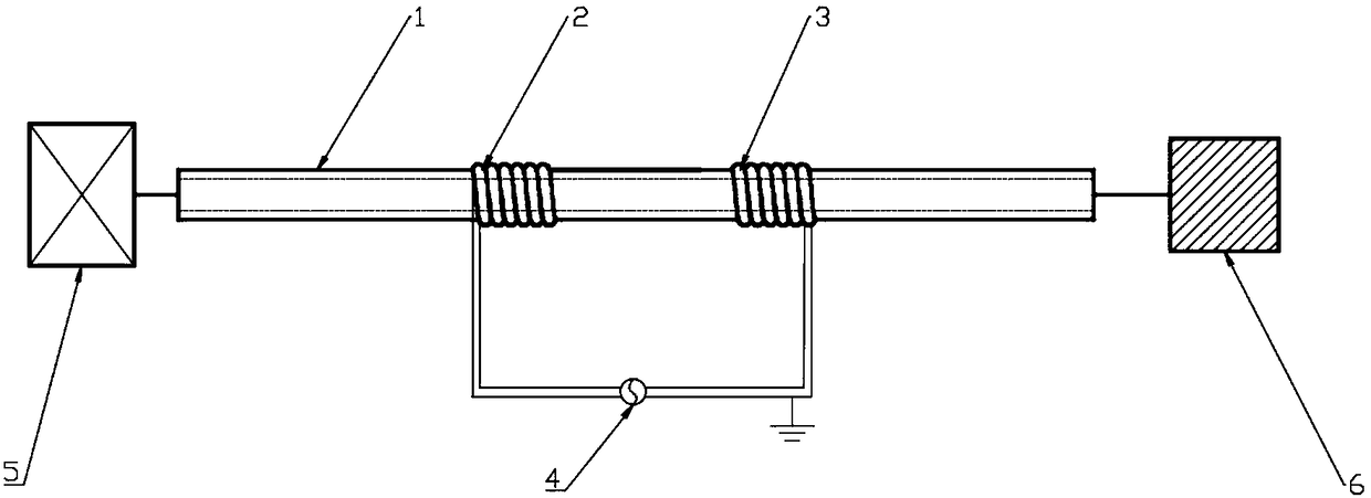
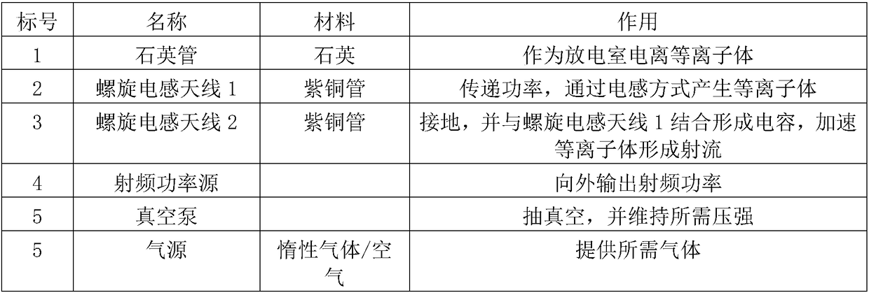
[0023] As shown in the figure, the device includes a quartz tube, a helical inductive antenna 1, a helical inductive antenna 2, a radio frequency power source, a vacuum pump and a gas source. It can realize the ionization and acceleration of plasma in a wide pressure range under radio frequency conditions.

[0024] In the specific implementation, it is necessary to pay attention to whether the connector of the RF cable is tightened, the cable is bent as naturally as possible, the core wire at the end of the output cable is closely connected with the electrode, and the wire between the two is as short as possible. Pay attention to the tight seal between the vacuum pump, the barometer, the quartz tube and the gas source.

[0025] In the specific implementation, the reflected power should be adjusted to be as small as possible.

[0026] In the specific implementa...


PUM


Abstract

A blocked inductance-capacitance coupling helical plasma antenna is disclosed. The invention discloses a plasma antenna device capable of acquiring a stable plasma jet flow in a wide air pressure range. The antenna is formed by two helical inductor antennas which are wound on a quartz tube. A helical inductor antenna 1 is connected to the anode of a radio frequency power supply. A helical inductorantenna 2 is grounded. The two segments of antennas are separated by a certain distance. The antenna has air blocking and forms an axial voltage drop in a capacitance mode to accelerate plasmas so asto obtain a high-speed jet flow. The structure of the antenna is simple and compact. The ionization of the plasmas and acceleration are combined and ionization efficiency is high. The stable ionization can be realized in an air pressure range from 150Pa to 2500Pa. Technical guarantee is provided for realizing radio frequency plasma ionization under different air pressure conditions, and an application range is wide.

Description

Technical field: [0001] The invention relates to the field of plasma antennas, in particular to a plasma antenna discharge mode based on a radio frequency power source working under wide pressure conditions. Background technique: [0002] With the continuous development of the plasma industry, its application prospects in material processing, integrated circuits, micromachining, plasma propulsion, etc. are extremely broad. The existing discharge methods include capacitive coupling, inductive coupling and helical wave discharge. However, the air pressure of the above methods must be lower than 1Toor (133.3Pa) when discharging under radio frequency conditions, and stable discharge cannot be achieved under higher air pressure conditions. Invention content: [0003] The invention overcomes the disadvantages of the prior art, can realize stable discharge at radio frequency in a wide air pressure range, and obtain high ionization efficiency and jet velocity. [0004] To achiev...

Claims


Application Information

Patent Timeline
Patent Type & Authority Applications(China)
IPC IPC(8): H01Q1/36
Inventor 苌磊胡馨月
Owner SICHUAN UNIV
Why Eureka
Try Eureka