Underwater pipe polishing device

An underwater pipeline and pipeline technology, which is applied in the directions of grinding machines, grinding/polishing equipment, metal processing equipment, etc., can solve the problems that the operation efficiency cannot meet the operation requirements, the operation environment is dangerous, and the skill requirements are high, and the adaptability of a certain pipe diameter can be achieved. , High cleaning efficiency, the effect of improving cleaning efficiency

Active Publication Date: 2018-10-12
BEIJING INSTITUTE OF PETROCHEMICAL TECHNOLOGY
View PDF9 Cites 6 Cited by
  • Summary
  • Abstract
  • Description
  • Claims
  • Application Information

AI Technical Summary

Problems solved by technology

Manual operation is that divers carry coating cleaning tools to manually clean the pipeline coating. This method is dangerous in the working environment and has low working efficiency; the underwater ROV manipulator with brush operation method requires high skills of the operator and low working efficiency
The operating efficiency of the two methods cannot meet the operating requirements of the current emergency

Method used


Image

  • Underwater pipe polishing device
  • Underwater pipe polishing device
  • Underwater pipe polishing device

Examples


specific Embodiment approach

[0014] The preferred embodiment of the underwater pipeline grinding device of the present invention is:

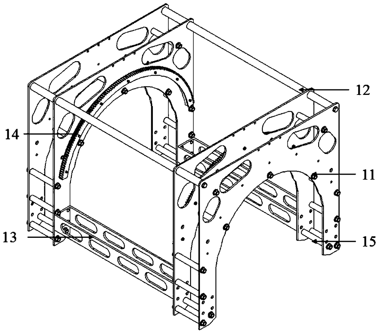
[0015] Including the equipment frame structure, the equipment frame structure includes a rack shell, the rack shell includes four aluminum alloy plates, the middle two aluminum alloy plates are connected by frame connecting rods and transverse connecting plates, and the two ends of the two The aluminum alloy plates are connected by frame mounting bolts, and the inner surfaces of the two aluminum alloy plates in the middle are provided with ring gears;

[0016] A pipe clamping mechanism is provided between the two aluminum alloy plates at both ends, and a walking brushing mechanism is provided between the two aluminum alloy plates in the middle.

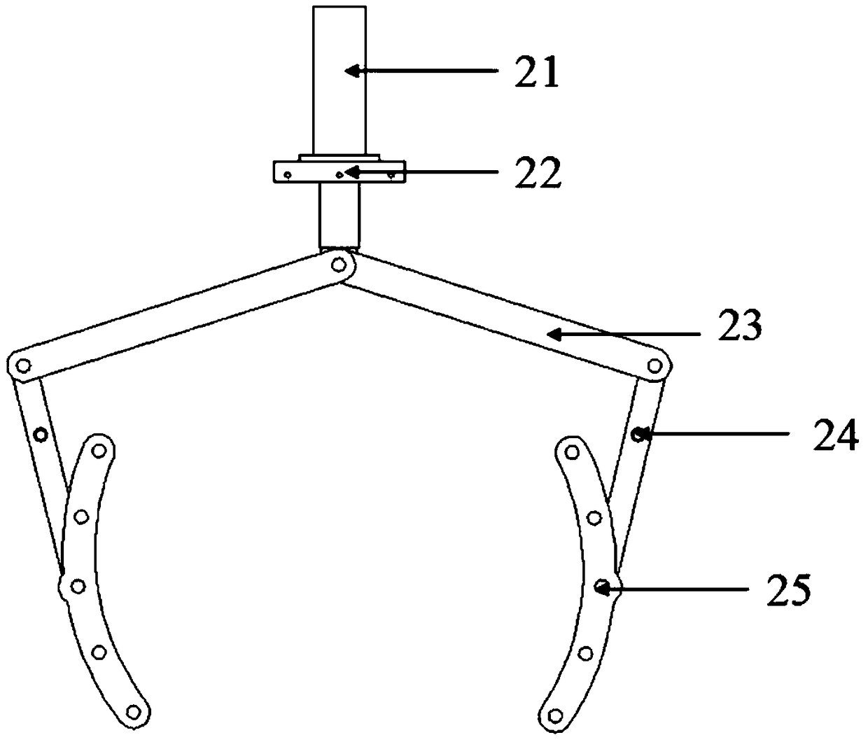
[0017] The pipeline clamping mechanism includes a clamping hydraulic cylinder and a clamping hydraulic cylinder mounting frame, the cylinder rod of the clamping hydraulic cylinder is connected with a pair of connecting rod clampin...

specific Embodiment

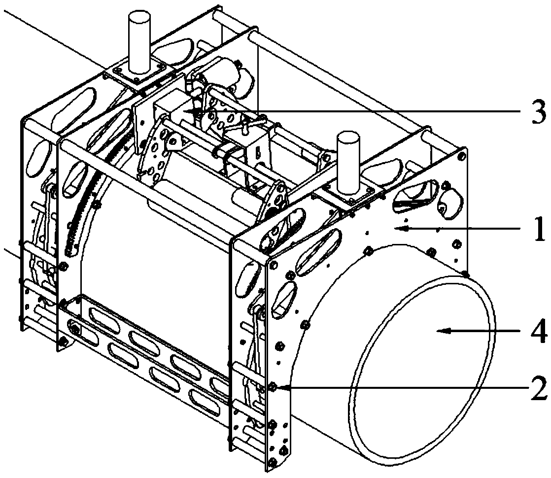
[0024] Such as Figure 1 to Figure 4 As shown, it includes an equipment frame structure 1, a pipe clamping mechanism 2 is provided in the middle of the frame shells 11 on both sides of the equipment frame structure 1, and a walking brushing mechanism 3 is provided at the inner end of the equipment frame structure 1.

[0025] The equipment frame structure mainly includes a frame shell 11 , frame connecting rods 12 , transverse connecting plates 13 , ring gear 14 , and frame mounting bolts 15 .

[0026] The pipeline clamping mechanism mainly includes a clamping hydraulic cylinder 21, a clamping hydraulic cylinder mounting frame 22, an upper rod member 23 of a linkage mechanism, a connecting rod rotating shaft support 24, and a clamping wheel support 25.

[0027] The brush tube mechanism mainly includes a wire brush hydraulic motor 37, a steel brush bracket 315, a steel brush fixing plate 36, a structural support frame 31, a traveling hydraulic motor 312, a reducer 313, a traveli...


PUM


Abstract

The invention discloses an underwater pipe polishing device for cleaning underwater seabed pipe protective coating layers. The underwater pipe polishing device comprises three parts of an equipment frame structure, a pipe clamping mechanism and a walk pipe brushing mechanism. The underwater auxiliary positioning is firstly performed on the underwater pipe polishing device through a ROV (remotely operated underwater vehicle), so that the equipment frame structure and target pipes are primarily positioned; then, the pipes are clamped by the pipe clamping mechanism, so that the device and the target pipes are totally positioned; the walk pipe brushing mechanism drives a steel wire brush roller to peripherally move; and finally, the steel wire brush roller is rotated to clean coating layers onthe surfaces of the pipes. The underwater pipe polishing device can be fixed on the pipes in multiple positions, and meanwhile, can realize 180-degree rotation through gear transmission, so that thecleaning efficiency of the coating layers and rust on the surfaces of the pipes is improved, and the engineering progress is accelerated.

Description

technical field [0001] The invention relates to a device capable of cleaning underwater pipeline coatings and rust, in particular to an underwater pipeline grinding device. Background technique [0002] In the complex and harsh seabed environment, a series of factors such as seawater corrosion, seabed organism adhesion, and anchor impact will cause chemical or physical damage to submarine oil pipelines, resulting in crude oil leakage, which will cause huge damage to the environment. Submarine pipelines need to be repaired in case of emergencies. There are many maintenance methods at present, but because submarine pipelines are often covered with various protective coatings, the coating on the surface of the pipeline needs to be removed before maintenance. [0003] Traditional coating cleaning methods generally use underwater manual operations or underwater ROV manipulators with brushes. Manual operation is that divers carry coating cleaning tools to manually clean the pipel...

Claims


Application Information

Patent Timeline
Patent Type & Authority Applications(China)
IPC IPC(8): B24B27/033B24B27/00
CPCB24B27/003B24B27/033
Inventor 高辉胡盼胡俊伟刘凯龙凃晏阁
Owner BEIJING INSTITUTE OF PETROCHEMICAL TECHNOLOGY
Why Eureka
Try Eureka