Grinding machine for optical fiber cable manufacturing

A fiber optic cable and grinding machine technology, which is applied in the direction of grinding machine tools, grinding devices, manufacturing tools, etc., can solve the problems of affecting the working environment, flying and putting in grinding residues, etc.

Inactive Publication Date: 2018-10-12
YICHANG HONGQI ZHONGTAI CABLE CO LTD
View PDF8 Cites 1 Cited by
  • Summary
  • Abstract
  • Description
  • Claims
  • Application Information

AI Technical Summary

Problems solved by technology

[0003] The purpose of the present invention is: in order to solve the present optical fiber grinding machine in the prior art when grinding the optical fiber, there will be grinding residues, but the present optical fiber grinding machine lacks a certain cleaning device in time, and these grinding residues remain on the optical fiber The grinding turntable of the grinding machine will affect the precision of the grinding machine for optical fiber grinding, and the grinding residue will also fly around, which will also make the surroundings of the optical fiber grinding machine look dirty, affecting the working environment and putting problems into it. Proposed Grinding Machine for Fiber Optic Cable Manufacture

Method used


Image

  • Grinding machine for optical fiber cable manufacturing
  • Grinding machine for optical fiber cable manufacturing
  • Grinding machine for optical fiber cable manufacturing

Examples


Embodiment Construction

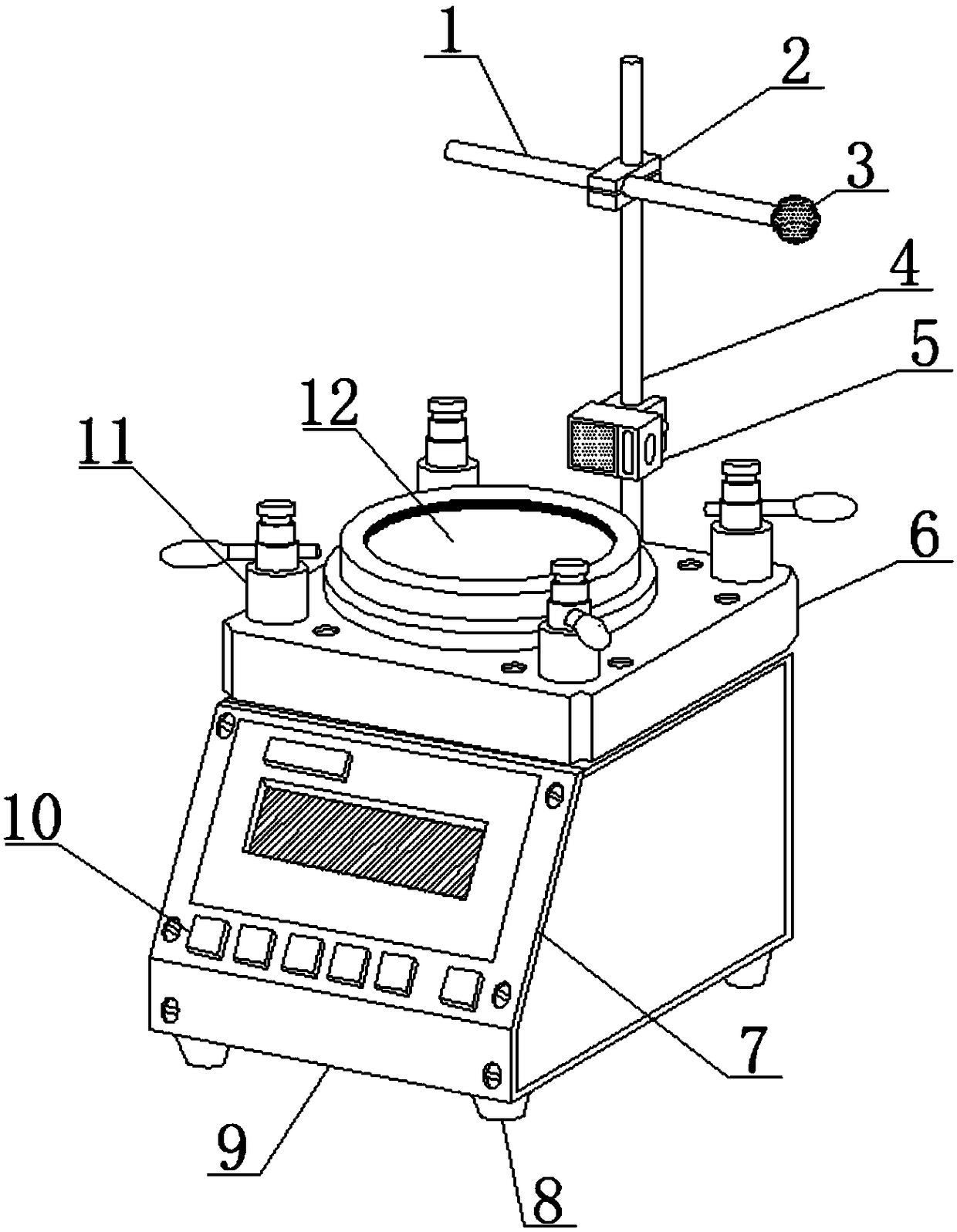
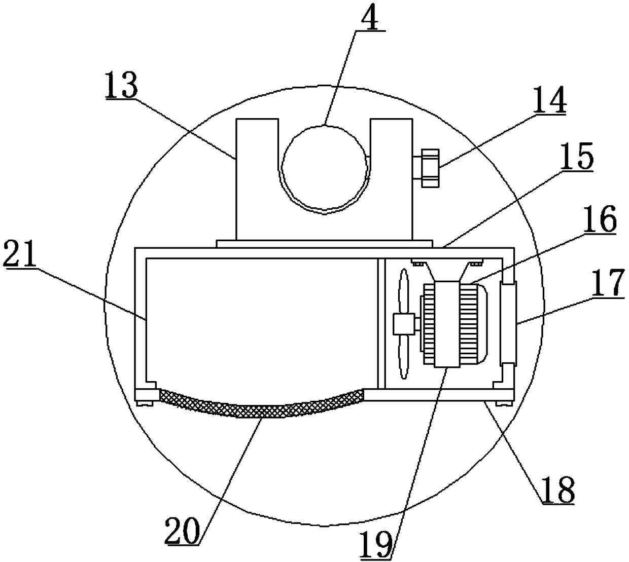
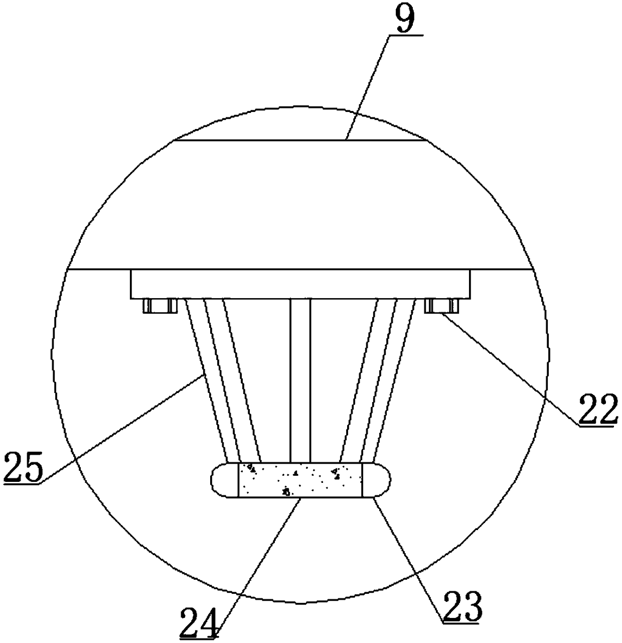
[0029] Such as Figure 1-Figure 6 As shown, a grinding machine for optical fiber cable manufacturing includes a magnetic support 8, the magnetic support 8 is installed at the four corners of the lower end of the body 9, the front of the body 9 is fixed with an end face 7 by a nut, and the end face 7 is relative to the position of the body 9. The other side is provided with a control switch 10, the upper end of the body 9 is provided with a grinding table 6, the upper center of the grinding table 6 is provided with a grinding turntable 12, and the four corners of the upper end of the grinding table 6 are provided with fixing devices around the grinding turntable 12. 11. There is a vertical rod 4 directly behind the body 9 and the grinding table 6, and the vertical rod 4 is fixed on the body 9. The middle position of the vertical rod 4 is buckled with a dust suction device 5, and the position in front of the upper end of the vertical rod 4 is A cross bar 1 is provided, and the u...


PUM


Abstract

The invention discloses a grinding machine for optical fiber cable manufacturing. The grinding machine comprises a magnetic bracket; the magnetic bracket is mounted at four corners of the lower end ofa machine body; an end surface is fixedly arranged in front of the machine body through a nut; a control switch is arranged on the other surface, corresponding to the end surface, of the machine body; a grinding table is arranged at the upper end of the machine body; a grinding turntable is arranged in the center position of the upper end of the grinding table; fixing devices are arranged at fourcorners of the upper end of the grinding table and positioned around the grinding turntable; stand rods are arranged behind the machine body and the grinding table, and are fixed on the machine body;dust sucking devices are buckled in the middle positions of the stand rods; cross bars are arranged in the front positions of the upper ends of the stand rods; the stand rods and the cross bars are fixedly connected through connecting heads; and spherical sleeves sleeve the right ends of the cross bars. The grinding machine prevents movement of an optical fiber grinding machine during working, isconvenient for the optical fiber grinding machine to grind optical fibers, and improves the use performance of the optical fiber grinding machine.

Description

technical field [0001] The invention relates to the technical field of a grinding machine for manufacturing optical fiber cables, in particular to a grinding machine for manufacturing optical fiber cables. Background technique [0002] Optical fiber grinding machine is a special equipment for grinding various optical fiber connector products, mainly used for grinding the end face of optical fiber ceramic ferrule, such as optical fiber jumper, pigtail, bundled optical fiber, PLC splitter plus head, energy optical fiber, Plastic optical fiber, pre-embedded short ferrule of optical fiber devices, etc., are widely used in the optical communication industry and are irreplaceable equipment. The relatively mature production line mode of modern enterprises is four or five optical fiber grinding machines and various specifications of FC / SC / LC / ST / MPO / MTRJ / MU grinding fixtures, optical fiber curing furnace, end face detector, pneumatic crimping machine . Insertion return loss tester ...

Claims


Application Information

Patent Timeline
Patent Type & Authority Applications(China)
IPC IPC(8): B24B37/10B24B37/34B24B55/06G02B6/38
Inventor 黎春陈明刘虎黄宗姣
Owner YICHANG HONGQI ZHONGTAI CABLE CO LTD
Why Eureka
Try Eureka