High-temperature superconductive vacuum pipeline traffic system with suspension and driving system arranged externally and smooth inner wall

A drive system, high-temperature superconducting technology, applied in tunnel systems, tracks, roads, etc., can solve the problem of not giving specific solutions for pipe wall structure and vehicle installation, not being able to achieve supersonic speed, super high speed, and not giving thin walls Pipeline strengthening and other issues to achieve the effect of reducing construction and operating costs, reducing requirements, and eliminating heat sources

Inactive Publication Date: 2018-10-12
XIJING UNIV
View PDF18 Cites 1 Cited by
  • Summary
  • Abstract
  • Description
  • Claims
  • Application Information

AI Technical Summary

Problems solved by technology

[0003] Existing vacuum pipeline transportation technology solutions are all based on the basic concept of placing existing railways and maglev in pipelines, and their common feature is that their tracks, power and suspension systems are all inside the pipeline, such as the patent "Vacuum Railway" (US1336732 ), "Vacuum Tube Transportation System" (US2511979), "Apparatus for Vacuum Tube Transportation" (US2488287), "Vacuum Pipeline High-speed Traffic Operation Air Pumping System" (CN200910305962.7), "Vacuum Pipeline High-speed Traffic Mobile Isolation Door Setup" (CN200910306188 .1), "Vertical moving isolation door for vacuum pipeline traffic" (CN200910219090.2), "Vacuum pipeline traffic split-type mobile isolation door setting" (CN201010300062.6), "A rotary gas isolation door for vacuum pipeline traffic Gate station and the method of entering and exiting the pipeline in the middle" (CN201710172741.1), "A method and system for a subway system used as a vacuum pipeline traffic branch line and a station" (CN201710398387.4), "An oval single-tube two-way vacuum pipeline transportation System" (CN201710876815.X), its disadvantages are: the suspension and power system generate heat, which will form heat accumulation in the pipeline; installation, inspection and maintenance must be carried out in the pipeline, which is very inconvenient and costly; it is not convenient to use more efficient The method of vacuuming, such as the piston-type pushing and exhausting method given in the patent "A Method and Device for Forming a Vacuum for Pipeline Traffic by Pushing and Exhausting Piston Vehicles" (CN201710398386.X)
[0004] The patent "Vacuum-tube Mass-transit System" (US4184792) provides a smooth vacuum pipeline transportation system inside the pipeline, but this system relies on aerodynamics and cannot achieve supersonic and superhigh speed, at most it is a pneumatic pipeline logistics system , does not belong to the category of modern vacuum pipeline transportation
[0005] The patent "Maglev transportation system with external power system thin-walled vacuum pipeline" (CN201010192101.5) provides a technical route for external suspension and drive system, but the track and support structure are still kept in the pipeline, and the inner wall is not completely smooth, which is not conducive to the adoption of Such as high-efficiency vacuum formation methods such as piston push exhaust; the patent also does not provide measures and solutions for strengthening thin-walled pipelines
[0006] The patent "A Method and Device for Pushing and Exhausting a Piston Vehicle to Form a Vacuum for Pipeline Traffic" (CN201710398386.X) gives the idea of ​​a smooth vacuum pipeline transportation system, but does not give a specific plan for the structure of the pipe wall and the installation of vehicles

Method used


Image

  • High-temperature superconductive vacuum pipeline traffic system with suspension and driving system arranged externally and smooth inner wall
  • High-temperature superconductive vacuum pipeline traffic system with suspension and driving system arranged externally and smooth inner wall
  • High-temperature superconductive vacuum pipeline traffic system with suspension and driving system arranged externally and smooth inner wall

Examples


Embodiment approach 1

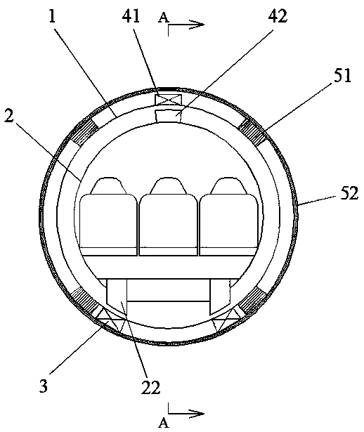
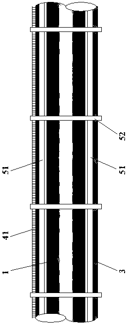
[0025] Such as figure 1 , figure 2 , image 3 As shown, a high-temperature superconducting vacuum pipeline transportation system with a circular pipeline section, an external suspension and drive system, and a smooth inner wall. It includes a pipeline 1, a vehicle 2, a permanent magnet track 3, a linear motor stator 41, a linear motor mover 42, a pipe rib 51, and a pipe collar 52.

[0026] Pipe 1 has a circular cross-section, smooth inner wall, and very thin pipe wall (less than 2mm). It is made of non-magnetic (does not affect the magnetic field, does not magnetize) light-weight high-strength materials such as stainless steel, aluminum alloy, titanium alloy, carbon nanotubes or graphene. Made of materials with good airtightness. In order to improve the strength of the pipe wall and ensure that the pipe 1 does not deform under the action of external pressure and dynamic load, the present invention provides the arrangement of pipe ribs 51 and pipe collars 52 . The pipe rib...

Embodiment approach 2

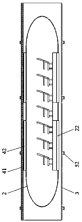
[0034] Such as Figure 4 As shown, a high temperature superconducting vacuum pipeline transportation system with an elliptical pipeline section, external suspension and drive system, and smooth inner wall. Its included content and setting are similar to the above-mentioned scheme one, which is characterized in that the section of the pipeline 1 is oval, the section of the vehicle 2 is oval, circular or rectangular, and the rectangular profile 6 formed by four support rollers 23 in the parallel plane of the section The length of the diagonal line 61 is greater than the length of the minor axis 7 of the elliptical duct 1, such as Figure 5 As shown, in order to prevent the vehicle from rotating and rolling in the pipeline 1 when the suspension system fails.

[0035] In a word, the solution provided by the present invention can effectively reduce the construction difficulty of vacuum pipeline transportation, facilitate inspection and maintenance, and significantly reduce the con...


PUM


Abstract

A high-temperature superconductive vacuum pipeline traffic system with a suspension and a driving system arranged externally and a smooth inner wall comprises a pipeline, a vehicle, a permanent magnetrail, a linear motor stator, a rotor, pipe ribs and pipe hoops. The section of the pipeline is circular or oval, the inner wall is smooth, and the pipeline wall is thin and made of non-magnetic high-strength materials; the gravity center of the vehicle is located on the lower half of the pipeline, the permanent magnet rail is located at the bottom outside the pipeline and corresponds to liquid nitrogen Dewars of the vehicle, and the permanent magnet rail is attached to the pipeline wall. The pipe ribs arranged in the longitudinal direction of the pipeline wall are fixedly connected with the pipe hoops arranged in the circumferential direction of the pipeline, so that the pipeline is not deformed. The high-temperature superconductive vacuum pipeline traffic system has the advantages that avacuum creating condition is formed by adopting a piston type pushing-pressing exhaust method, internal power thermal sources of the pipeline are eliminated, and construction installation and checking and repairing can be conveniently completed outside the pipeline; and the pipe ribs and the pipe hoops are used for reinforcing the pipeline wall to prevent warping and instability, so that building, operation and maintenance costs of the vacuum pipeline are effectively lowered.

Description

technical field [0001] The invention belongs to the technical field of vacuum pipeline transportation, and in particular relates to a high-temperature superconducting vacuum pipeline transportation system with two external suspension and drive systems with a smooth inner wall. Background technique [0002] Human beings have never stopped pursuing speed. Today's high-speed rail and maglev are all restricted by air resistance, aerodynamic noise, and aerodynamic vibration, and cannot further increase their speed. In addition to being affected by air resistance, aircraft and automobiles consume a lot of energy and carbon emissions, and their future development will be limited. Vacuum tube high-speed transportation overcomes the above-mentioned shortcomings. It is a transportation mode that can reach ultra-high speed, has low energy consumption, and has little environmental impact. It is expected to fundamentally solve the dilemma faced by human transportation. Vacuum pipeline t...

Claims


Application Information

Patent Timeline
IPC IPC(8): B61B13/10B60L13/04
CPCB61B13/10B60L13/04
Inventor 张耀平
Owner XIJING UNIV
Why Eureka
Try Eureka