
Bar code scanning chip and scanning method

A barcode scanning and chip technology, which is applied in the field of barcode scanning chips and scanning, can solve the problems of weak reflected light signal of scanning code, high frequency of code scanning failure, low signal contrast, etc., to solve fuzzy barcode, improve signal-to-noise ratio, improve efficiency effect

Active Publication Date: 2018-10-12
SHENZHEN UNIV
View PDF6 Cites 2 Cited by
  • Summary
  • Abstract
  • Description
  • Claims
  • Application Information

AI Technical Summary

Problems solved by technology

However, the response speed of the traditional PN junction photodetector is low, and it is not sensitive to weak light. The collected scanning reflected light signal is weak, resulting in low signal contrast, poor stability, and high frequency of scanning failures.

Method used


Image

  • Bar code scanning chip and scanning method
  • Bar code scanning chip and scanning method
  • Bar code scanning chip and scanning method

Examples


Embodiment 3

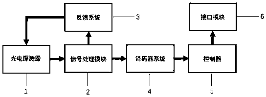
[0044] This embodiment provides a barcode scanning method, which uses the barcode scanning chip described in the above embodiment, such as Figure 5 As shown, the method specifically includes:

[0045] S10. The photodetector collects the reflected laser signal, converts the laser signal into a first photoelectric signal, and transmits the first photoelectric signal to a signal processing module;

[0046] S20. The signal processing module converts the first photoelectric signal into a first barcode wave, and outputs the first barcode wave to a feedback system;

[0047] S30. The feedback system calculates the noise equivalent power of the first photoelectric signal according to the first barcode wave, and applies a bias voltage to the photodetector according to the noise equivalent power;

[0048] S40. The biased photodetector transmits the collected second photoelectric signal to the signal processing module;

[0049] S50. The signal processing module converts the second phot...


PUM


Abstract

The application discloses a bar code scanning chip and scanning method. The bar code scanning chip comprises a photoelectric detector, a signal processing module, a feedback system, a decoder system,a controller and an interface module, wherein the photoelectric detector is connected with the signal processing module, the signal processing module is sequentially connected with the decoder systemand the controller to form a scanning branch, the signal processing module is connected with the feedback system to form a feedback branch, and the feedback system acts on the photoelectric detector and is used for acquiring the noise equivalent power of photoelectric signals collected by the photoelectric detector and applying a bias voltage to the photoelectric detector according to the noise equivalent power. According to the scheme of the application, the feedback system is additionally arranged, the noise equivalent power of the photoelectric signals is calculated through the feedback system, and the bias voltage is applied to the photoelectric detector according to the calculated noise equivalent power, so that a signal-to-noise ratio can be improved, the light response rate and thebrightness of collected light can also be ensured, and the efficiency and accuracy of code scanning can be further improved.

Description

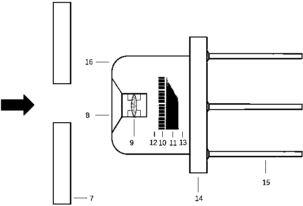
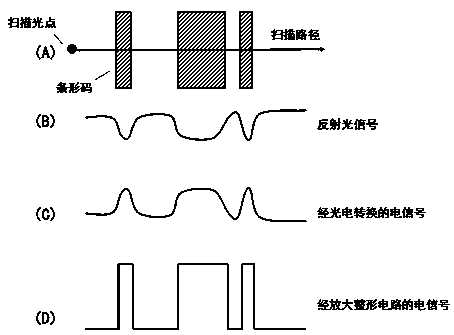
technical field [0001] The present application relates to the technical field of scanning chips, in particular to a barcode scanning chip and a scanning method. Background technique [0002] The scanning chip in the existing barcode scanning equipment generally includes a photodetector, a decoder system, a controller and an interface module. The reflected light is detected by the photodetector and photoelectrically converted to obtain a photoelectric signal. The controller and the interface module send the information carried by the photoelectric signal to the external device. Wherein, the detector generally adopts relatively mature commercial photoelectric sensors, such as silicon-based diode photosensors, CdS semiconductor detectors, metal-silicon Schottky photodetectors, and the like. However, the response speed of the traditional PN junction photodetector is low, and it is not sensitive to weak light. The collected scanning reflected light signal is weak, resulting in l...

Claims


Application Information

Patent Timeline
Patent Type & Authority Applications(China)
IPC IPC(8): G06K7/10
CPCG06K7/10722G06K7/10831G06K7/10851
Inventor 张希曹志鹏陈文聪刁东风
Owner SHENZHEN UNIV
Learn More