Spiral heating tube structure

A heating tube and spiral technology, which is applied in the field of spiral heating tube structures, can solve the problems of inconvenient installation and disassembly of the spiral heating tube, and achieve the effects of reducing work complexity, avoiding work hazards and having a simple structure.

Pending Publication Date: 2018-10-12
盐城中自科技有限公司
View PDF0 Cites 2 Cited by
  • Summary
  • Abstract
  • Description
  • Claims
  • Application Information

AI Technical Summary

Problems solved by technology

[0004] Aiming at the deficiencies of the prior art, the present invention provides a spiral heating tube s

Method used


Image

  • Spiral heating tube structure
  • Spiral heating tube structure

Examples


Embodiment Construction

[0018] The following will clearly and completely describe the technical solutions in the embodiments of the present invention with reference to the accompanying drawings in the embodiments of the present invention. Obviously, the described embodiments are only some, not all, embodiments of the present invention. Based on the embodiments of the present invention, all other embodiments obtained by persons of ordinary skill in the art without making creative efforts belong to the protection scope of the present invention.

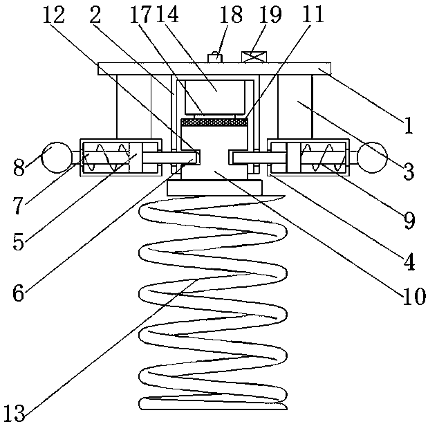
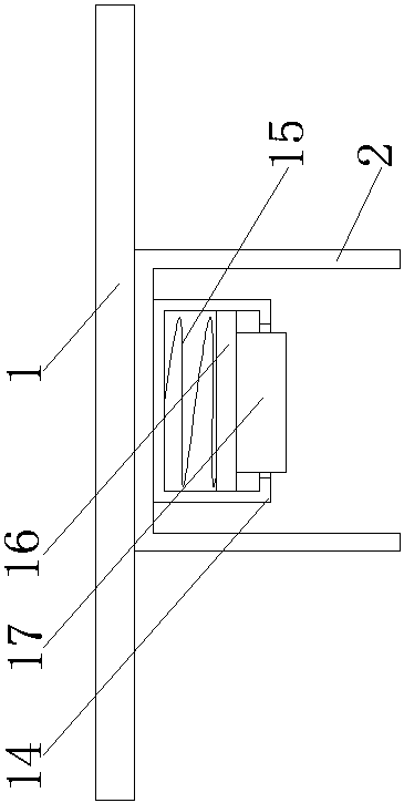
[0019] see Figure 1-2 , the present invention provides a technical solution: a spiral heating tube structure, including a coupling plate 1, the middle of the bottom of the coupling plate 1 is fixedly connected with a clamping frame 2, and the bottom of the clamping frame 2 is open for the entry and exit of the clamping block 10, combined Both sides of the bottom of the plate 1 and both sides of the clamping frame 2 are fixedly connected with the connecting bl...


PUM


Abstract

The invention discloses a spiral heating tube structure. The spiral heating tube structure comprises a combination plate, wherein a clamping frame is fixedly connected to a middle part of the bottom of the combination plate, connection blocks are fixedly connected to two sides of the bottom of the combination plate and are arranged at two sides of the clamping frame, a fastening box is fixedly connected to the bottom of each connection block, a sliding plate is connected to the fastening box in a sliding way, a clamping plate is fixedly connected to one side of the sliding plate, one side of the clamping plate sequentially penetrates through the fastening box and the clamping frame and extends to the clamping frame, and an extending rod is fixedly connected to the other side of the slidingplate. The spiral heating tube structure relates to the technical field of a heating tube. By the spiral heating tube structure, the condition that a spiral heating tube is inconvenient to install, disassemble and maintain is solved, the operation complexity of an operator is effectively reduced, the operation of a worker is greatly facilitated, installation failure caused by operation complexityis prevented, and moreover, the spiral heating tube structure is simple in structure and is convenient to operate.

Description

technical field [0001] The invention relates to the technical field of heating tubes, in particular to a spiral heating tube structure. Background technique [0002] An electric heater refers to an electrical appliance that uses electric energy to achieve a heating effect. It is small in size, high in heating power, and widely used. It adopts intelligent control mode, has high temperature control accuracy, and can be networked with a computer. Wide range of applications, long life and high reliability. The core of the heater principle is energy conversion, the most common is the conversion of electrical energy into heat energy, the heating tube is filled with electric heating wire in a seamless metal tube (carbon steel tube, titanium tube, stainless steel tube, copper tube), and the gap is filled with It is made of magnesium oxide powder with good thermal conductivity and insulation, and then processed into various shapes required by users. It has simple structure, high t...

Claims


Application Information

Patent Timeline
IPC IPC(8): H05B3/02H05B3/42
CPCH05B3/02H05B3/42
Inventor 王海兵
Owner 盐城中自科技有限公司
Why Eureka
Try Eureka