Flue dust desulfurizing device for thermal power generation plant

A technology for thermal power plants and soot, applied in gas treatment, dispersed particle separation, membrane technology, etc., can solve the problems of polluted air and insufficient gas desulfurization, and achieve the effects of environmental protection, compact structure, vibration and noise reduction

Inactive Publication Date: 2018-10-16
张丽聪
View PDF6 Cites 1 Cited by
  • Summary
  • Abstract
  • Description
  • Claims
  • Application Information

AI Technical Summary

Problems solved by technology

[0004] The object of the present invention is to make up for the deficiencies of the prior art, and to provide a smoke and dust desulfurization device for thermal power plants, which has the function of stirring the desulfurization catalyst before the flue gas desulfurization and then using it for desulfurization to make the smoke and dust desulfurization efficiency high In flue gas desulfurization, the high-temperature flue gas is first cooled to make the low-temperature flue gas desulfurization more fully, and after the flue gas desulfurization, the impurities and harmful gases in the flue dust are removed by filtering the flue gas to fully protect the environment, which solves the existing problem The desulfurization catalyst is not fully activated before the wet desulfurization of thermal power generation, the temperature of the smoke and dust is not cooled during desulfurization, and the dusty gas is directly discharged after desulfurization, resulting in insufficient desulfurization of the gas and the problem of air pollution caused by impurities and other harmful gases

Method used


Image

  • Flue dust desulfurizing device for thermal power generation plant
  • Flue dust desulfurizing device for thermal power generation plant
  • Flue dust desulfurizing device for thermal power generation plant

Examples


Embodiment Construction

[0032] The following will clearly and completely describe the technical solutions in the embodiments of the present invention with reference to the accompanying drawings in the embodiments of the present invention. Obviously, the described embodiments are only some, not all, embodiments of the present invention. Based on the embodiments of the present invention, all other embodiments obtained by persons of ordinary skill in the art without making creative efforts belong to the protection scope of the present invention.

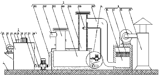
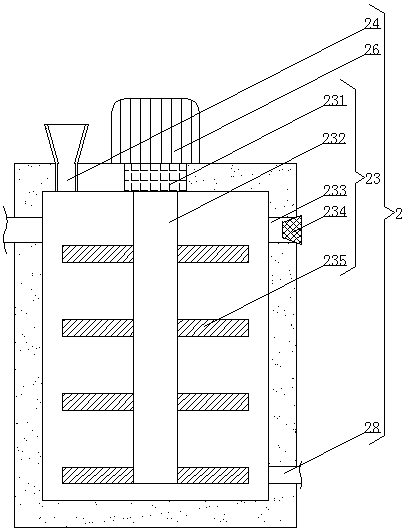
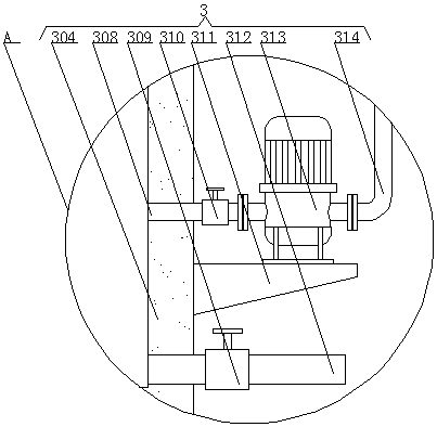
[0033] see Figure 1-4 , the present invention provides a technical solution: a smoke and dust desulfurization device for thermal power plants, including a base 1, the left side of the upper surface of the base 1 is fixedly connected with a stirring mechanism 2, and the middle part of the upper surface of the base 1 is fixedly connected with a cooling The spray mechanism 3, and the cooling spray mechanism 3 is located on the right side of the stirring mechanis...


PUM


Abstract

The invention discloses a flue dust desulfurizing device for a thermal power generation plant, and relates to the technical field of thermal power generation. The flue dust desulfurizing device comprises a base, wherein the left side of the upper surface of the base is fixedly connected with a stirring mechanism; the middle part of the upper surface of the base is fixedly connected with a coolingand spraying mechanism; the cooling and spraying mechanism is positioned at the right side of the stirring mechanism; the right side of the upper surface of the base is fixedly connected with a discharge mechanism; the discharge mechanism is positioned at the right side of the cooling and spraying mechanism. The flue dust desulfurizing device for the thermal power generation plant has the advantages that by arranging the stirring mechanism, under the function of an air blower, a desulfurizing catalyst is fully stirred and mixed with a sodium carbonate solution and air, the stirred desulfurizing solution is completely activated, and the sulfur-containing flue dust is completely desulfurized; by arranging a cooling pipeline, the temperature of the flue dust before desulfurizing is reduced, and the flue dust is more fully desulfurized; by arranging a filtering box, the desulfurized gas is fully filtered, the desulfurized flue gas is cleaner, and the environment is effectively protected.

Description

technical field [0001] The invention relates to the technical field of thermal power generation, in particular to a smoke and dust desulfurization device for thermal power plants. Background technique [0002] Thermal power generation is a power generation method that uses the heat generated by combustibles during combustion and converts it into electrical energy through a power generation device. It is the main power generation method in our country, but thermal power generation pollutes seriously, and the electric power industry has become one of the largest polluting industries in our country. [0003] Existing coal-fired thermal power generation contains a large amount of sulfur in the flue gas after coal combustion. If these sulfur-containing flue gas is directly discharged into the atmosphere, it will cause pollution and form acid rain. In order to protect the environment, the sulfur-containing flue gas is not allowed to be discharged directly. In the atmosphere, ther...

Claims


Application Information

Patent Timeline
Patent Type & Authority Applications(China)
IPC IPC(8): B01D53/86B01D53/50
CPCB01D53/8609B01D2258/0283
Inventor 张丽聪
Owner 张丽聪
Why Eureka
Try Eureka