Industrial robot demonstration device based on six freedom degree

A technology of industrial robots and demonstration devices, applied in the direction of instruments, chemical instruments and methods, cleaning methods using gas flow, etc., can solve the problems of high maintenance costs, high product prices, expensive diamonds, etc., and achieve the effect of optimizing the working environment

Inactive Publication Date: 2018-10-16
HECHI UNIV
View PDF0 Cites 3 Cited by
  • Summary
  • Abstract
  • Description
  • Claims
  • Application Information

AI Technical Summary

Problems solved by technology

[0002] The existing industrial workpiece engraving devices are all simple engraving machines, which require manual real-time feeding and unloading, which consumes a lot of time and manpower; and the existing engraving methods mainly include the following three types: The first method is , use the water jet to spray the abrasive to the working surface, but the equipment of this method occupies a large area, and the efficiency of processing small workpieces is low, and the engraved patterns cannot be handled carefully. In addition, the control of the water jet also requires expensive control system
The second method is to directly use diamond to process the workpiece, but due to the high price of diamond, when engraving a large number of workpieces, the loss of diamond will be fast, and the maintenance cost will be high, so that the price of the product will be high.
The third way is to make a good engraving pattern mold, and then process the tool through the oscillator, but making the mold is time-consuming and laborious, and the efficiency is not high enough
Moreover, these methods are not accurate enough in the prior art and the efficiency is not high.

Method used


Image

  • Industrial robot demonstration device based on six freedom degree
  • Industrial robot demonstration device based on six freedom degree
  • Industrial robot demonstration device based on six freedom degree

Examples


Embodiment Construction

[0024] The specific implementation of the invention will be further described below in conjunction with the accompanying drawings.

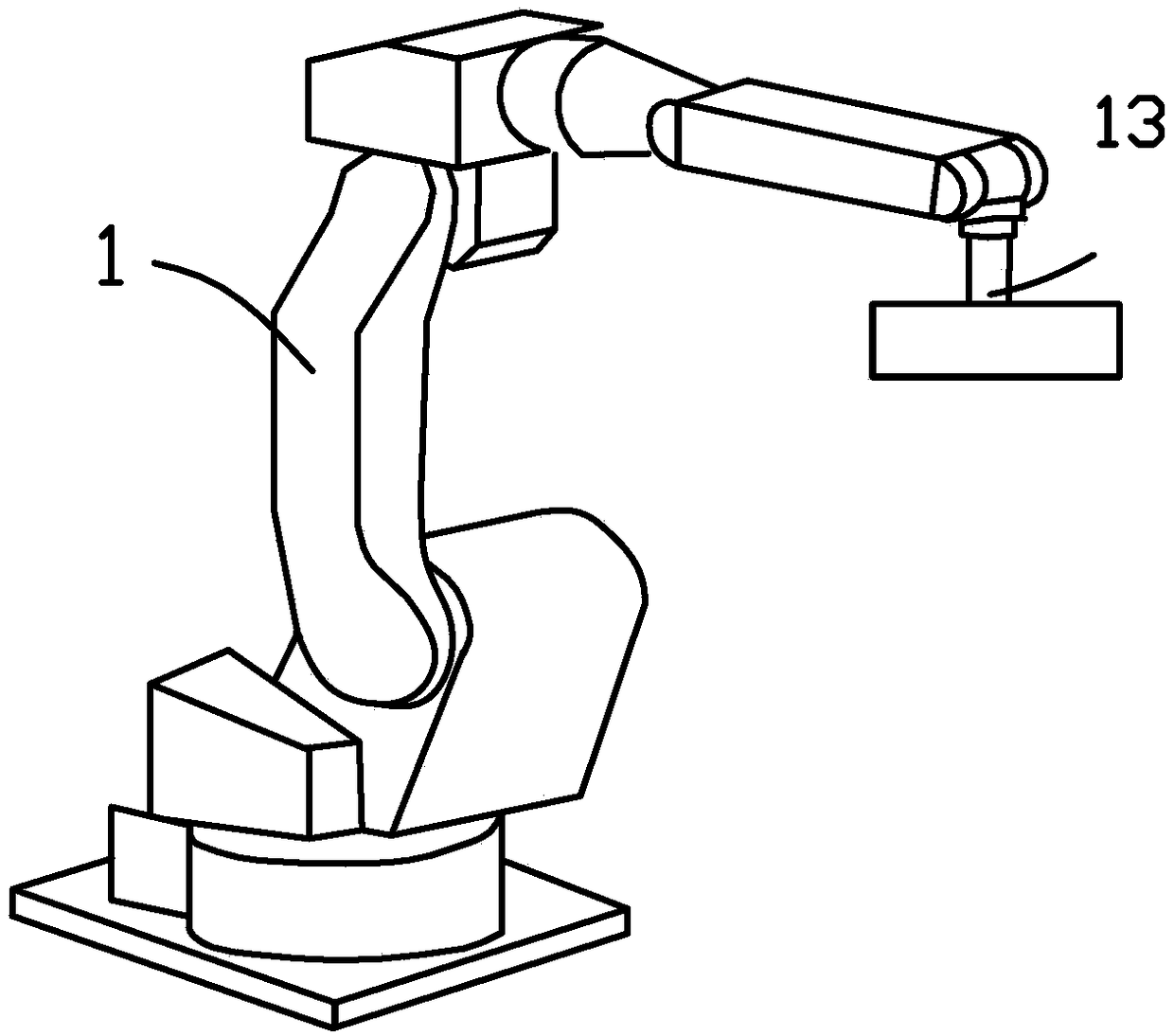
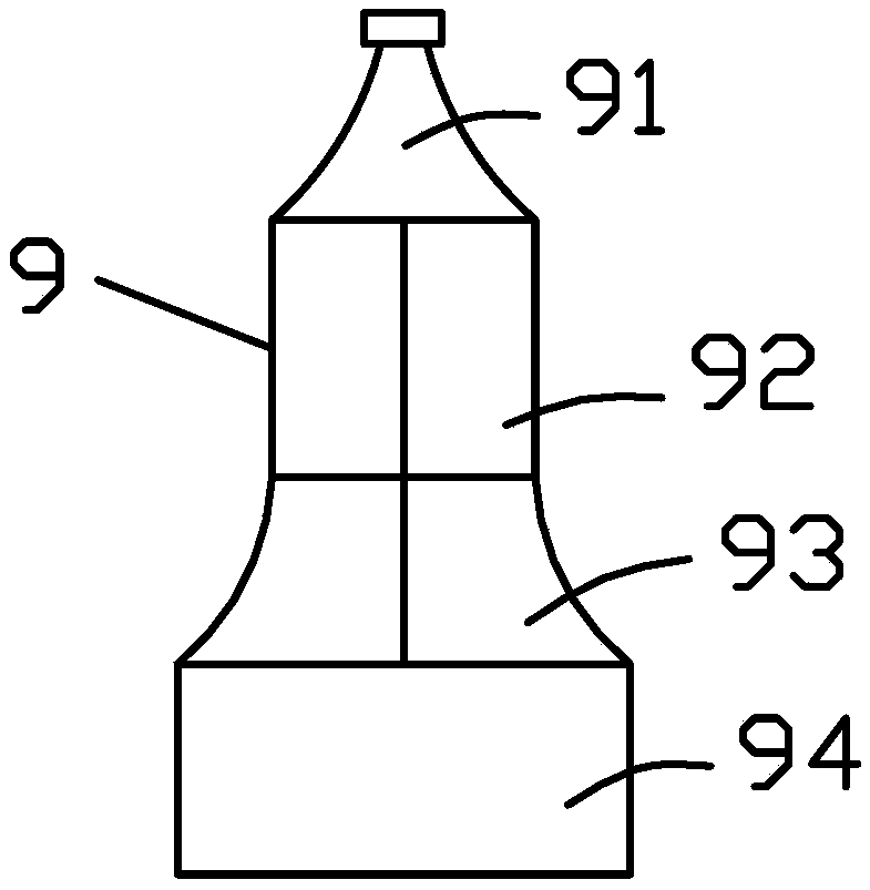
[0025] Such as figure 1 Shown is a working arm 11 with a preset working program, which is a six-degree-of-freedom industrial robot in the prior art; the movement of the working arm 11 can be controlled by the manipulator, and the working arm 11 can also move according to the set action. The fixture 13 includes a fixture 13 body and a pneumatic claw, and the fixture 13 body is correspondingly fixed on the clamping end of the working arm. The bottle mouth portion 91, a rectangular portion 92, and a column corresponding to the workpiece electronic model 9 are respectively provided on the fixture 13 body. Part 93 and the clamping port of the clamping part, and the pneumatic claws are in one-to-one correspondence with the clamping port.

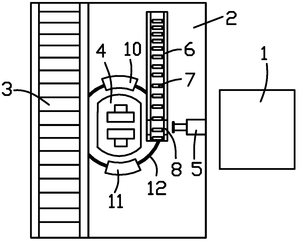
[0026] Such as figure 2 As shown, the pushing device includes a base 2, a conveyor belt 3, a clamping seat 4 an...


PUM


Abstract

The invention discloses an industrial robot demonstration device based on six freedom degree, and belongs to the technical field of industrial robot demonstration teaching. The system comprises a pushing device, a polishing electronic model and an air micro grinder electronic model, wherein the polishing electronic model is in a polishing product shape and successively comprises a rectangular part, a round ball part, an upright column part and a clamping part from top to bottom, thin film pressure sensors are uniformly laid on the outer-side surfaces of the round ball part, rectangular part and upright column part, the thin film pressure sensors are connected with a processing module arranged in the clamping part, and the processing module is further connected with a wireless module installed in the clamping part; the air micro grinder electronic model comprises a rotating head and an air leg body, the air leg body is connected with an external air supplying device and is arranged at the clamping end of a working arm, the rotating head can be driven by the air leg body to rotate, and the rotating head is made from elastic materials. The system can carry out demonstration teaching visually, simulate multiple polishing conditions, show the stress conditions in the polishing process, and make students conveniently know operating conditions.

Description

technical field [0001] The invention relates to the technical field of industrial robot demonstration teaching, in particular to an industrial robot demonstration device based on six degrees of freedom. Background technique [0002] The existing industrial workpiece engraving devices are all simple engraving machines, which require manual real-time feeding and unloading, which consumes a lot of time and manpower; and the existing engraving methods mainly include the following three types: The first method is , use the water jet to spray the abrasive to the working surface, but the equipment of this method occupies a large area, and the efficiency of processing small workpieces is low, and the engraved patterns cannot be handled carefully. In addition, the control of the water jet also requires Expensive control system. The second method is to directly use diamond to process the workpiece, but due to the high price of diamond, when engraving a large number of workpieces, the...

Claims


Application Information

Patent Timeline
Patent Type & Authority Applications(China)
IPC IPC(8): G09B25/02B08B5/04
CPCG09B25/02B08B5/04
Inventor 彭建盛覃勇韦庆进何奇文林元明彭金松
Owner HECHI UNIV
Why Eureka
Try Eureka