Fuse structure circuit and its forming method

A fuse structure and fuse technology, applied in circuits, electrical components, electric solid devices, etc., can solve the problems that the performance of metal fuses cannot meet the requirements, and achieve the effect of reducing the fusing current and improving performance

Active Publication Date: 2021-02-02
SEMICON MFG INT (SHANGHAI) CORP +1
View PDF3 Cites 0 Cited by
  • Summary
  • Abstract
  • Description
  • Claims
  • Application Information

AI Technical Summary

Problems solved by technology

[0004] As the integration of integrated circuits continues to decrease, the performance of metal fuses is difficult to meet the requirements

Method used


Image

  • Fuse structure circuit and its forming method
  • Fuse structure circuit and its forming method
  • Fuse structure circuit and its forming method

Examples


Embodiment Construction

[0033] As mentioned in the background, the performance of the fuse structure circuit formed in the prior art is difficult to meet the requirements.

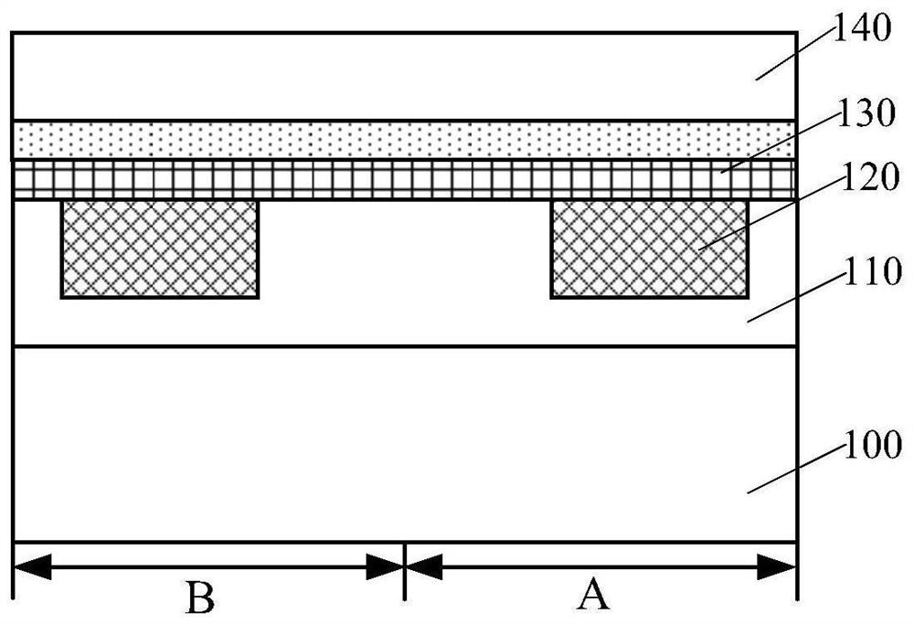
[0034] figure 1 It is a structural diagram of a fuse structure circuit, and the fuse structure circuit includes: a substrate 100, the substrate 100 includes a fuse area A and a control area B; a first interlayer dielectric layer 110 located on the base 100; The metal layer 120 in the first interlayer dielectric layer 110 in the area A and the first interlayer dielectric layer 110 in the control area B; the cover layer 130 located on the top surface of the metal layer 120; the second interlayer dielectric located on the cover layer 130 Layer 140.

[0035] However, the performance of the above-mentioned fuse structure circuit is poor. After research, it is found that the reasons are:

[0036] Fuse structure circuits are used to be embedded in integrated circuits. There are several transistors in the fuse structure circuit, at le...


PUM

PropertyMeasurementUnit
thicknessaaaaaaaaaa
thicknessaaaaaaaaaa
thicknessaaaaaaaaaa

Abstract

A fuse structure circuit and its forming method, wherein the method includes: providing a base, the base includes a fuse area and a control area; respectively forming a metal layer on the base fuse area and the control area, and the metal layer of the control area is used to be electrically connected to the metal layer of the fuse area; a first cover layer is formed on the top surface of the metal layer of the fuse area, and the material of the first cover layer and the material of the metal layer of the fuse area have a first bonding energy; The top surface of the metal layer in the control area forms a second covering layer, the material of the second covering layer and the material of the metal layer in the control area have a second binding energy, and the first binding energy is smaller than the second binding energy. The method results in improved performance of the fuse structure circuit.

Description

technical field [0001] The invention relates to the field of semiconductor manufacturing, in particular to a fuse structure circuit and a forming method thereof. Background technique [0002] In the semiconductor industry, fuse elements are widely used in integrated circuits due to their multiple uses. For example, multiple circuit modules with the same function are designed in the integrated circuit as a backup. When one of the circuit modules is found to be invalid, the circuit module and other functional circuits in the integrated circuit are blown through the fuse element, and the circuit module with the same function is used. Another circuit module replaces the failed circuit module. Another example is to design a general-purpose integrated circuit and blow out unnecessary circuit modules through fuse elements according to the needs of different users, so that an integrated circuit can be manufactured in an economical way and suitable for different customers. [0003]...

Claims


Application Information

Patent Timeline
Patent Type & Authority Patents(China)
IPC IPC(8): H01L21/768H01L23/525
CPCH01L21/76832H01L23/5256
Inventor 甘正浩冯军宏
Owner SEMICON MFG INT (SHANGHAI) CORP
Why Eureka
Try Eureka